Use Cases
Use Cases¶
Power Transformer Case Study¶
This case study mainly illustrates the Property Classes Pattern. Information on other patterns is included in the case study, but is not a focus. It shows why different Property Types are needed and how they attach to the correct Bearers across the lifecycle of a High Voltage Power Transformer (referred to as a power transformer in this study). It uses the power transformer as a running example to distinguish between properties of different bearers. Hint: An instance of a property cannot "live" without its bearing instance e.g. the instance 380 kV of rated voltage cannot exist without the bearer which is an instance of a power transformer identified by the property serial number which as well cannot exist without the instance of the power transformer. Examples of bearers in this case study are —
-
physical objects,
-
activities performed by those objects,
-
events in the lifecycle of those objects,
-
organizations which contribute to the lifecycle of those objects,
-
locations where those objects will be materialized during the lifecycle,
-
documents attached or related to those objects,
-
financial objects as connection to the accounting of the participating organization.
Note
Function is not mentioned here because it is like a property --- a dependent class, which needs a bearer --- and a function cannot have properties which is defined like this in the IDO.
Furthermore, it also demonstrates how Required, Rated, Nominal, Measured and Calculated (properties that are derived from other properties) values coexist, how geographical information (e.g. Country of Installation) is modeled using governed Reference Properties, and how external code systems such as ISO 3166-1 "Codes for the representation of names of countries and their subdivisions — Part 1: Country code" are incorporated using Classification Properties. The case study is designed to feed the Competency Questions of the PropertyClasses pattern.
Visual Overview — From Core to Operational Transformer¶
To provide a clear visual foundation for the Power Transformer case study, the following figures illustrate the physical object across its lifecycle — from the first assembly steps of the magnetic core, through winding production, installation and operation, to dismantling and recycling. These images help readers connect the physical features of a transformer with the different property types (Quality, Reference, Classification, etc.) discussed later in this case study. They are not part of the ontology itself, but serve as a visual anchor for the semantics developed in the following chapters.
Magnetic core assembly¶
Stacking of laminated steel sheets to form the magnetic core of a three-phase power transformer is shown in Figure 1. The core limbs will later carry the windings and provide the magnetic path that links the three phase systems.
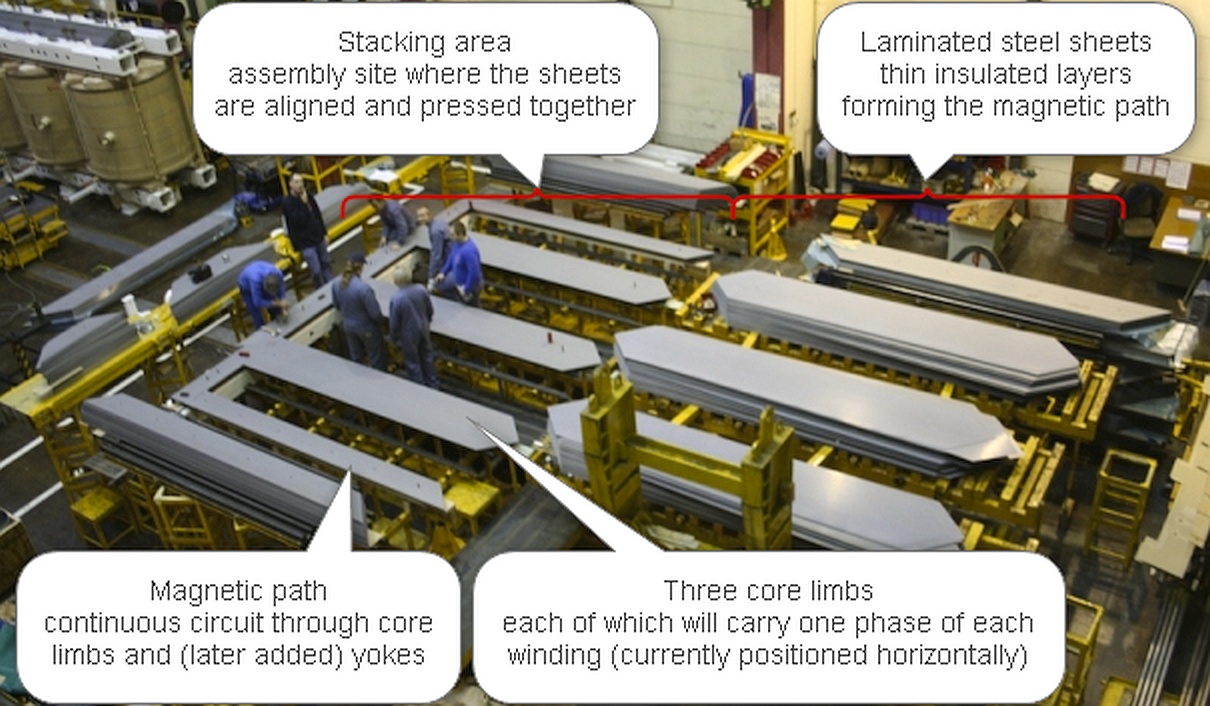
This view shows the beginning of the Power Transformer’s physical lifecycle. The three horizontally positioned core limbs, each carrying one phase of the high- and low-voltage windings, form the magnetic structure that will later determine the Rated Power and Rated Voltage of the Power Transformer.
Winding assembly on the magnetic core¶
Figure 2 shows the copper windings being mounted on the core limbs. The conductors and layer insulation are visible. The transformer is a fluid-insulated type, designed for oil-based insulation and cooling.
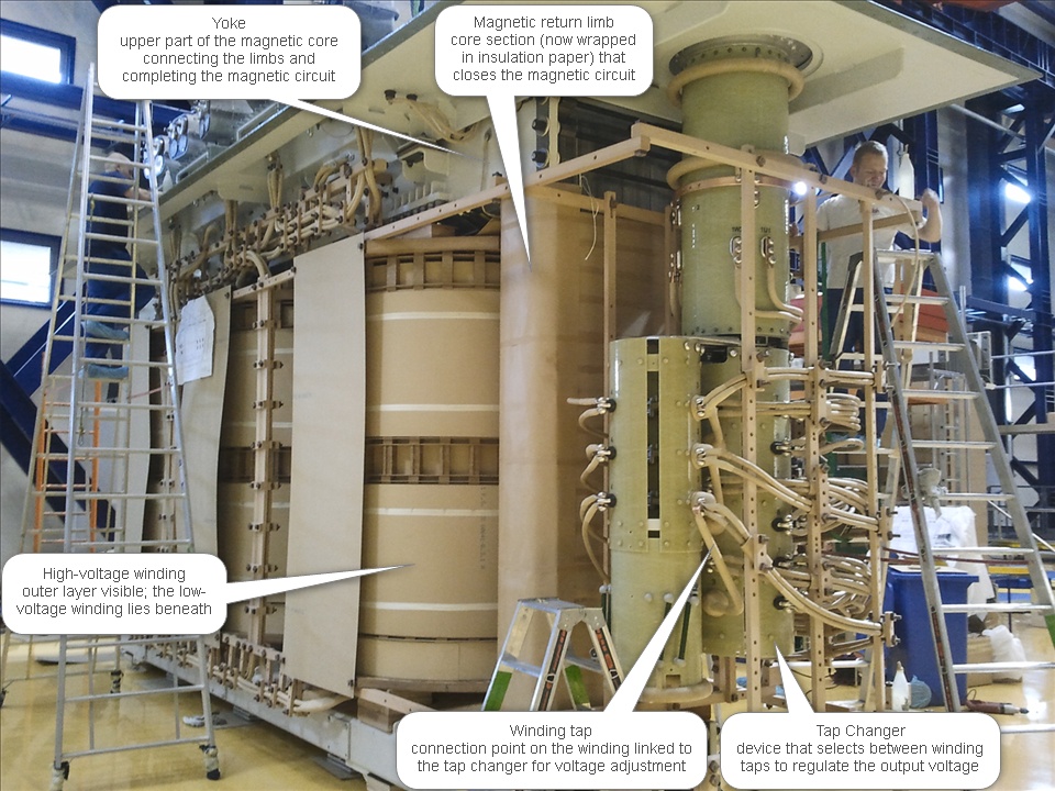
At this stage, the windings are being assembled and insulated around the core. The visible tap-changer leads connect to tapped sections that will later allow regulation of the output voltage. Here, physical Quality Properties such as Rated Voltage, Rated Power and Cooling Method begin to take form as intrinsic, design-defined characteristics of the manufactured transformer.
An installed power transformer in operation¶
Figure 3 illustrates an installed step-down transformer (approx. 400 MVA, 380 / 110 kV) at the EnBW Großgartach substation in Germany. The unit shows high- and low-voltage bushings, a neutral terminal, cooling radiators, and an oil conservator tank for thermal compensation.
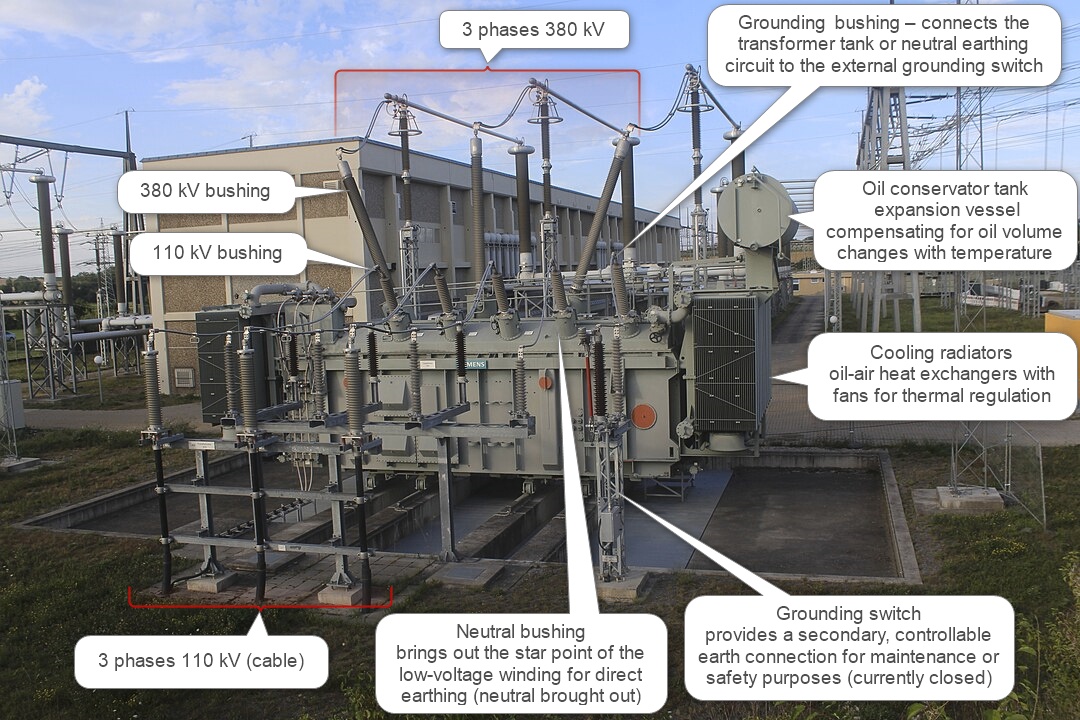
The fully assembled and oil-cooled transformer is shown in a ready-for-service state (it is not energized, as the grounding switch is closed). The bushings, cooling system and oil conservator demonstrate how mechanical and insulation features support electrical operation. This image corresponds to the operational phase in which Nominal and Measured Properties become relevant while the Rated Properties from design remain the capability limits of the asset.
Transformer end-of-life dismantling¶
Figure 4 depicts a power transformer being dismantled during end-of-life processing. With the tank removed, the copper windings and insulation structure are exposed, showing the internal active parts before material separation and recycling. Visually, the same appearance can occur during manufacturing or major refurbishment, when the active part is assembled or re-insulated.
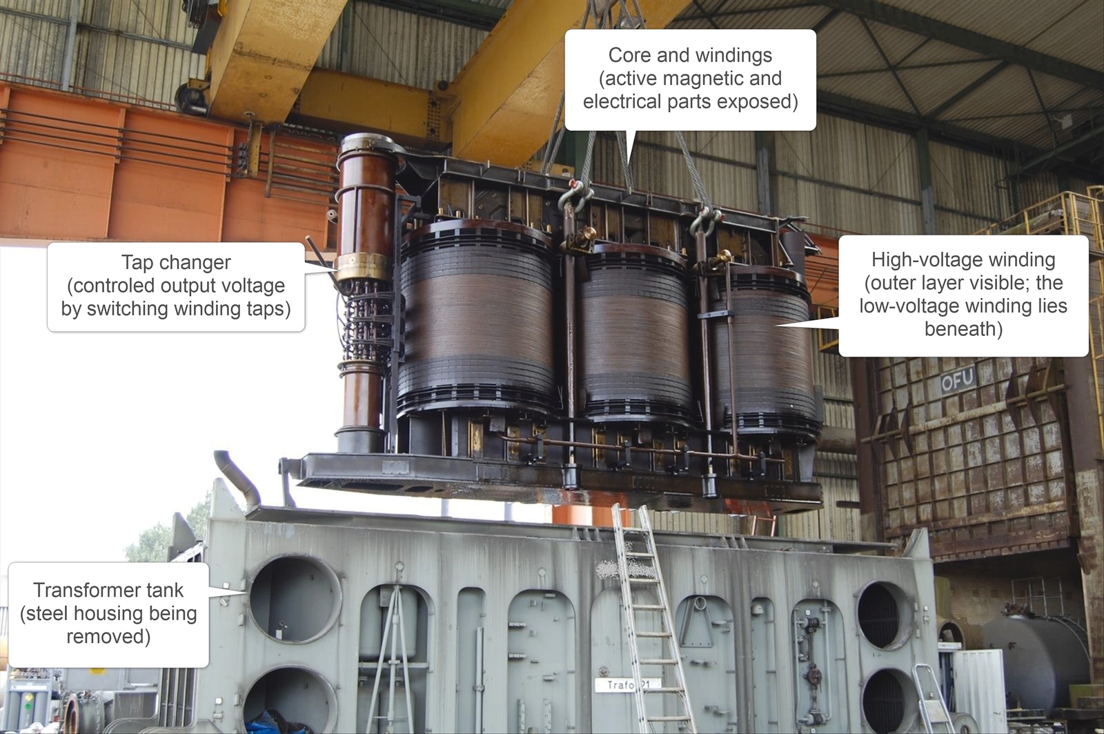
This image illustrates the physical end-of-life phase of a power transformer, when the active part is dismantled for inspection or recycling. This stage is not explicitly modeled in this case study; it is shown here only to complete the visual representation of the transformer’s full physical lifecycle. No new properties are introduced or referenced for this phase — the image merely provides a realistic impression of how the same internal structure reappears when the transformer is disassembled at the end of service or during major refurbishment.
Lifecycle Context and Narrative¶
This section explains, phase by phase, how properties arise, how they change, and which entity (Bearer) legitimately "has" which property in each stage, from planning to operation. The scenario is international by design: the Power Transformer is manufactured in Austria, installed in Germany, owned and operated by a Japanese utility, and remotely monitored by an operations service team based in Brazil. This produces cross-border dependencies: technical requirements, legal and jurisdictional obligations, logistics and customs, and operational responsibilities cannot be treated in isolation. The story also follows the modeling distinction between the different bearers mentioned in the previous chapter.
Design and Specification Phase¶
A new high-voltage substation is being built in Germany. Its purpose is to hand over electrical power from the 380 kV transmission grid into the 110 kV regional high-voltage network. This substation is part of a broader grid expansion program, needed to transport renewable energy inland and redistribute it across industrial and urban areas. The central component of the new substation is a step-down Power Transformer. It converts 380 kV from the transmission side to 110 kV on the regional side. The Power Transformer will become a registered asset and a key element of the national grid.
A transmission system operator is procuring this large three-phase Power Transformer for grid integration of a new wind park. Both engineering teams (at Owner/Operator, EPC and manufacturer) and ontology engineers must describe this power transformer in a way that is precise, machine-interpretable, and compliant with IEC 60076-1.
The system engineering team (ideally at the Owner/Operator side or at the EPC side) breaks down the overall requirement to transport electrical renewable energy from the producing wind park to the consumers. This includes the activity to transform the energy from the 380 kV transmission grid voltage to the 110 kV regional grid voltage. They specify the Nominal Power (380 MVA) and the Nominal Voltage levels (input: 380 kV / output: 110 kV). These are the values which should be fulfilled during operation. This is not yet a statement about the manufactured transformer as an object. It is a statement about the intended power-transfer activity in the system context.
The substation operates within a three-phase AC transmission network, as is typical for high-voltage power systems. From the perspective of the Owner/Operator, the key concern is to ensure that electrical energy can be transferred reliably between the transmission network (380 kV) and the regional high-voltage network (110 kV) without creating unwanted phase conflicts in the grid. For this reason, the Owner/Operator defines the required phase displacement between the primary and secondary systems as part of the system-level design requirements.
This requirement belongs to the Power Transfer Activity — it expresses how the voltages on the two network sides must be phase-aligned for proper synchronization and parallel operation with other transformers in the grid. In practical terms, this requirement is often stated as required phase shift and its phase displacement direction (leading or lagging, hint: the meaning will be explained in the next chapter), for example 30° lagging between the primary and secondary system voltages. The equipment engineer or manufacturer must interpret this activity-level requirement and derive from it the corresponding device-level properties of the transformer (such as winding connections and vector-group configuration) that realize the required phase relationship in practice (details see next chapter).
By formulating the requirement at the level of the Power Transfer Activity and deriving the physical implementation only later, the ontology can maintain a clear semantic distinction between what the system demands and how the equipment fulfils that demand. The equipment design team derives the specifications for the Power Transformer Specification from the given Power Transfer Activity. They specify the Specified Power (400 MVA, the engineers know that the specified power must be higher than the nominal power to have some buffer, hint: this rule should be considered in the ontology) and the Specified Voltage levels (380 kV / 110 kV). They choose a Cooling Method, Insulation Class, and Delivery Date. These are Specified Properties, defined in the design and procurement phase. They belong to the Purchase Order Item (Delivery Date, see chapter 11.2 for details) and the Requirement Specification of the Power Transformer Specification (Specified Power, Specified Voltage, Cooling Method, Insulation Class), not to the Physical Power Transformer.
Ontology requirement at this stage¶
Bearers identified
-
Power Transfer Activity — the operational activity representing energy transfer between voltage levels;
-
Power Transformer Specification — the collection of the specified properties (was in the past a specification document, with additional structure information it would be possible to generate a document out of the specified properties);
-
Purchase Order — the contractual artefact linking commercial and technical requirements.
Property assignment
-
Nominal properties (e.g. Nominal Power, Nominal Voltage) are assigned to the Bearer Power Transfer Activity;
-
Configuration properties (e.g. Required Phase shift, Phase Displacement Direction, Voltage Conversion Role) are assigned to the Bearer Power Transfer Activity too;
-
Specified properties (e.g. Specified Power, Specified Voltage, Cooling Method, Insulation Class) are assigned to the Bearer Power Transformer Specification;
-
Details about
Delivery Dateand how it is assigned to the BearerPurchase orderis defined in Procurement and Logistics.
Note
All these properties, including Delivery Date, are qualifying the bearer.
Rules identified
These make knowledge explicit — which is implicit in the Power Transformer story.
-
Nominal Power and Nominal Voltage describe intended system behavior, not device capability.
-
Specified Power ≥ Nominal Power (as engineering margin).
-
Voltage Conversion Role is step-up if the voltage of the incoming electrical energy is lower than that of the outgoing electrical energy, and step-down if it is the opposite (as defined in IEC 60076-8). It describes the functional role of the power-transfer activity within the electrical grid.
Notes
-
These properties belong to the requirement level; rated and measured values appear only after design and testing.
-
Quantitative details such as value + unit (MVA, kV, A) or lists of values (e.g., lagging, leading or 0°, 30°, 60° … 330°) are treated in Pattern P2 or P5, not within the Property Classes Pattern.
-
The teams mentioned (e.g., Owner/Operator, System Engineering, Procurement) represent organizational bearers rather than technical ones. Their ontology requirements are addressed separately in Organizational and Project Context.
Manufacturing Phase¶
After procurement, the selected Manufacturer takes responsibility for the detailed design and production of the Power Transformer. Within the manufacturer’s organization, the Engineering Team defines the rated design data in accordance with IEC 60076-1, while the Manufacturing Team fabricates the physical asset according to these design definitions. The Power Transformer is a physical asset that embodies its Rated Power and Rated Voltage — two fundamental design properties that describe its capability under standard operating conditions. These rated values are established by the Engineering Team during the design stage to ensure the transformer can operate continuously within the prescribed thermal and electrical limits defined by the standard.
Rated Properties¶
The Power Transformer is a physical asset that embodies its Rated Power and Rated Voltage — two fundamental design properties that describe its capability under standard operating conditions. These rated values are established by the Engineering Team during the design stage to ensure the transformer can operate continuously within the prescribed thermal and electrical limits defined by the standard.
Rated Power represents the continuous apparent power output the transformer can deliver under rated voltage, frequency, and cooling conditions. It is defined in design, verified once for the transformer type through the Temperature Rise Type Test on a representative prototype, and then applied to all assets of the same type. In practice, the Engineering Team typically defines the Rated Power slightly higher than the Specified Power defined during procurement — for example, a transformer specified at 400 MVA may receive a Rated Power of 410 MVA — to provide operational margin for thermal and load variations.
Rated Voltage defines the nominal voltage per winding that produces the rated voltage at the terminals of the other windings under open-circuit conditions. It, too, is fixed in the design and remains constant for all manufactured transformers of that type. During the design process at the Manufacturer, the Engineering Team defines the internal structure of the Power Transformer.
The Power Transformer comprises multiple windings, each being a physical sub-entity of the power transformer. Each winding is assigned its own Rated Voltage and Rated Current. Together, these properties describe the electrical behavior of that winding in the overall power transformer configuration. Typical designs include a high-voltage (HV) winding (winding which has a higher Rated Voltage than the other winding) and a low-voltage (LV) winding (winding which has a lower Rated Voltage than the other winding), possibly with one or more intermediate windings for regulating or tertiary functions. The resulting set of windings defines how electrical energy is transferred between voltage levels in operation.
Ontology requirement at this stage¶
Bearers identified
-
Power Transformer Specification — defines the rated electrical design properties; its values will be verified by type tests;
-
Power Transformer Type — prototype of a new power transformer series to verify the values defined in the specification and in IEC 60076; its type test protocol can be referenced by all Physical Power Transformers of the series the Power Transformer Type is built for
-
Physical Power Transformer — instantiates the type and is produced under the same rated conditions;
-
Winding — a physical sub-component (or in other words: a physical part) of the Power Transformer Type or the Physical Power Transformer.
Property assignment
-
Qualifying properties: rated properties (e.g. Rated Power, Rated Voltage, Rated Current) are assigned to the Bearers like Transformer Type or the part Winding;
-
The measured results that verify the rated properties are documented in the different Test Protocols (type test or factory acceptance test), which will later be associated with the manufactured power transformer via its Serial Number (see Chapter 11.1.2.5)
Rules identified
These make knowledge explicit which is implicit in the Power Transformer story:
-
Rated Power >= Specified Power > Nominal Power.
-
Rated properties must comply with IEC 60076-1 limits for thermal and electrical stress.
-
Rated and measured properties during the different test are related to each other.
-
The winding with the higher Rated Voltage is named HV and the winding with the lower Rated Voltage is named LV.
-
The part-of relation between Physical Power Transformer and Winding must be at least 2 (if it would be only 1 then it is a Shunt Reactor and not a Power Transformer)
-
The part-of relation between Winding and Physical Power Transformer must be exactly 1, because a winding cannot exist independently of a power transformer. Each winding instance is therefore a mandatory and uniquely associated part of exactly one power transformer instance.
Notes
-
Quantitative details such as value + unit (MVA, kV, A) are treated in Pattern P2, not within the Property Classes Pattern.
-
The teams mentioned (e.g., Engineering team) represent organizational bearers rather than technical ones. Their ontology requirements are addressed separately in Organizational and Project Context.
Winding design — From System Requirement to Device Design¶
Based on the required Phase Shift and Phase Displacement Direction defined by the Owner/Operator or System Engineering during the design and specification phase, the Engineering Team at the Manufacturer (or, in some cases, the Equipment Engineering Team at the EPC) determines how this requirement can be realized inside the transformer. To achieve the configured phase relationship between the primary and secondary windings, the engineers define the internal connection scheme of the transformer windings according to IEC 60076-1. These design decisions transform the requirement defined for the Power Transfer Activity into concrete device-level properties.
The Engineering Team translates the required Phase Shift and Phase Displacement Direction — for example, 30° lagging between the primary and secondary system voltages — into the corresponding Phase Displacement Group of the respective winding, following the standardized “clock notation” principle of IEC 60076-1 § 7.1.2. Each 30° of Phase Shift corresponds to one “hour” on the vector-group clock face. The phase displacement direction defines whether the hour numbering is counted clockwise (leading) or counter-clockwise (lagging) from the 12 o’clock reference position. This interpretation marks the point where the activity-level requirement from the Owner/Operator is converted into a device-level design intent that will later be expressed through the power transformer’s connection designation.
Ontology requirement at this stage¶
Bearers identified
-
Power Transfer Activity — provides the requirements which are relevant for the Power Transformer Specification;
-
Power Transformer Specification — the collection of the specified properties (was in the past a specification document, with additional structure information it would be possible to generate a document out of the specified properties);
Property assignment
- configuration properties (e.g., Specified Phase Displacement Group) are assigned to the Bearer Power Transformer Specification.
Note
All these properties are qualifying the bearer.
Rules identified
-
Phase Displacement Group must correspond to the required Phase shift and Phase Displacement Direction defined in the Power Transfer Activity;
-
Each 30° of phase shift equals one clock hour in IEC 60076-1 notation.
-
The phase displacement direction defines whether the hour numbering is counted clockwise or counter-clockwise
Notes
-
Quantitative details such as value + unit (°) or lists of values (lead, lag or 0, 1, 2 … 11) are treated in Pattern P2 or P5, not within the Property Classes Pattern.
-
The teams mentioned (e.g., System or Equipment Engineering team at the EPC, Engineering Team at Manufacturer) represent organizational bearers rather than technical ones. Their ontology requirements are addressed separately in Organizational and Project Context.
Three-Phase Construction and Connection Types¶
To realize this design property physically, the Engineering Team defines how the transformer windings must be arranged. The Power Transformer is therefore constructed as a three-phase transformer, in which each of its windings — high-voltage, low-voltage, and, if applicable, intermediate — consists of three single-phase windings, one for each phase of the electrical system. The way these three phase windings are interconnected determines how voltage and current are distributed across the phases and how the transformer interacts with the surrounding grid. The possible interconnections are called connection types, as defined in IEC 60076-1 § 7.1.1. Each connection type has distinct electrical characteristics and implications for insulation, grounding, and system compatibility:
-
Star (Y) — the three phase windings are connected to a common point, forming a neutral. This arrangement allows the use of phase-to-neutral voltages and provides grounding possibilities.
-
Delta (D) — the three windings are connected end-to-end in a closed loop. There is no neutral point, and phase-to-phase voltages dominate the behavior.
-
Zigzag (Z) — a more complex connection providing phase balancing and specific grounding features.
-
Auto (A) — a configuration where sections of windings are shared between voltage levels.
-
Open (III) — a special form used in open-winding arrangements.
If a winding is connected in Star (Y), the designer must additionally decide whether the neutral point is brought out to an external terminal. This property, called Neutral Brought Out, is only relevant for star-connected windings. Providing an accessible neutral enables grounding and auxiliary single-phase supplies, but it also affects insulation levels and test requirements.
Ontology requirement at this stage¶
Bearers identified
-
Power Transformer Specification — defined as three-phase asset ;
-
Winding Specification — have different connection types and could have Neutral Brought Out.
Property assignment
-
Configuration properties (e.g. Specified Connection Type, Specified Neutral Brought Out) are assigned to the Bearer Winding Specification.
-
Configuration properties (e.g. Specified Number of phases, Specified Winding Voltage Order) are assigned to the Bearer Power Transformer Specification.
Note
All these properties are qualifying the bearer.
Rules identified
-
If Connection Type = Star (Y), then Neutral Brought Out may be true or false;
-
If Connection Type ≠ Star, then Neutral Brought Out = false;
-
Symbols for windings must appear in descending order of Rated Voltage (IEC 60076-1 § 7.1.1).
Notes
-
Quantitative details such as boolean (e.g., Neutral Brought Out) or lists of values (e.g., Y, D, Z, A, III) are treated in Pattern P4 or P5, not within the Property Classes Pattern.
-
The teams mentioned (e.g., Engineering team) represent organizational bearers rather than technical ones. Their ontology requirements are addressed separately in Organizational and Project Context.
Phase Displacement and Connection Designation¶
After the winding interconnections have been defined, the overall electrical configuration of the transformer can be expressed as its Connection Designation, often referred to as the vector-group code (e.g. Dyn11, Yy0), as defined in IEC 60076-1 § 7.1.2. This designation is not a single textual label but a derived composite property that encodes the key configuration features of the transformer:
-
the Connection Type of each winding (Star, Delta, Zigzag, etc.);
-
whether a Neutral is brought out for the respective star-connected winding;
-
the Phase Displacement Group between the high-voltage and lower-voltage windings (expressed by the “clock number”); and
-
the Winding Voltage Order, which defines the sequence of windings by decreasing Rated Voltage.
Each 30° of phase shift corresponds to one “hour” on the vector-group clock face.
The Phase Displacement Direction determines whether the numbering of these hours is counted clockwise (leading) or counter-clockwise (lagging) from the 12 o’clock reference position, where the high-voltage winding is taken as the reference. For example, in the designation Dyn11, the “11” indicates that the low-voltage phase leads the high-voltage phase by 330°, equivalent to a 30° lagging displacement, as specified in the system requirement. IEC 60076-1 also requires that the symbols representing the individual windings appear in descending order of their Rated Voltages. This ensures that the Connection Designation remains consistent and unambiguous across manufacturers and projects.
In semantic terms, the Connection Designation is therefore a derived property — the result of combining explicitly modeled primitive configuration properties. It should not be treated as the single authoritative value in the ontology; instead, its component properties (Connection Type, Neutral Brought Out, Phase Displacement Group, Winding Voltage Order) must be represented individually, allowing the designation to be computed or serialized as needed.
Ontology requirement at this stage¶
Bearers identified
-
Winding Specification — defines the Connection Type and whether Neutral is Brought Out;
-
Power Transformer Specification — aggregates the phase-related configuration (Phase Displacement Group, Winding Voltage Order) and derives the overall Connection Designation.
Property assignment
-
Configuration properties (e.g. Connection Type, Neutral Brought Out) are assigned to the Winding Specification
-
Configuration properties (e.g. Phase Displacement Group, Winding Voltage Order) are assigned to the Power Transformer Specification
-
Derived configuration property (Connection Designation) are assigned to the Power Transformer Specification (functionally derived from the above primitive configuration properties)
Note
All these properties are qualifying the bearer.
Rules identified
-
If Connection Type = Star (Y), Neutral Brought Out may = true or false.
-
If Connection Type ≠ Star, Neutral Brought Out = false.
-
Phase Displacement Group must correspond to the required Phase Shift and Phase Displacement Direction defined in the Power Transfer Activity.
-
Symbols for windings must appear in descending order of Rated Voltage (IEC 60076-1 § 7.1.1).
-
Connection Designation is a derived serialization and must remain consistent with its component configuration properties.
Notes
-
The Connection Designation (e.g. Dyn11) acts as the standardized shorthand but is semantically derived.
-
Boolean and enumerated configuration values (e.g. Neutral Brought Out, Connection Type) are handled through controlled vocabularies and represented as categorical properties (see Patterns P4 and P5).
-
Organizational roles (Engineering Team, Equipment Design Team, Manufacturer) are not modeled here; they are addressed in Organizational and Project Context.
Identification and Classification¶
Once the power transformer has been manufactured according to its released design, the Manufacturing Team assigns a Serial Number. This Serial Number is an identifying property that uniquely refers to the specific physical transformer and enables traceability throughout its lifecycle — from testing and logistics to operation and decommissioning.
Note
The Serial Number becomes mandatory at the latest when preparing the data set for the transformer's nameplate.
To achieve global uniqueness, additional context such as the manufacturer’s identifier and year of manufacture can be combined with the Serial Number, since no global authority assigns unique transformer identifiers. The Serial Number also provides the formal traceability link to the transformer’s Test Protocols. Each Test Protocol documents the measured values obtained during testing, and this one-to-one association ensures that every set of test results can be unambiguously traced to the corresponding physical asset.
In general, Type Test Protocols and Factory Acceptance (Routine) Test Protocols refer to different transformers and therefore to different Serial Numbers. The Type Test Protocol validates the design of a transformer type on a representative unit, whereas the Factory Acceptance Test confirms compliance of each individually manufactured transformer prior to delivery. An exception occurs when the first manufactured transformer of a new type serves both as the representative unit for type testing and as the first asset delivered to a customer; in this case, both protocols share the same Serial Number. In parallel to identification, the finished unit is also classified according to standardized product taxonomies.
Two design properties — Rated Power and Insulation Type — determine the correct external class assignment in ECLASS. ECLASS (release 15.0) defines the following relevant transformer classes:
| Insulation Type | Rated Power Range | ECLASS Code | Preferred Class Name |
|---|---|---|---|
| Fluid | > 100 MVA | 27-03-12-01 | Transformer (oil cooled > 100 MVA) |
| Fluid | 10 — 100 MVA | 27-03-12-02 | Transformer (oil cooled, 10—100 MVA) |
| Fluid | \< 10 MVA | 27-03-12-03 | Transformer (oil cooled \< 10 MVA) |
| Dry | any MVA | 27-03-12-04 | Transformer (cast resin insulation) |
Because the transformer in this case study is fluid-insulated and has a Rated Power of 410 MVA, it belongs to class 27-03-12-01 “Transformer (oil cooled > 100 MVA)”. This classification connects the internally defined engineering properties with an externally governed reference vocabulary and allows interoperability across engineering, procurement, and asset-management systems.
Ontology requirement at this stage¶
Bearers identified
-
Physical Power Transformer — the manufactured, uniquely identified asset that will later be tested and delivered.
-
ECLASS Classification Class — an externally governed product class used for standardized classification (e.g. “Transformer (oil cooled > 100 MVA)”, IRDI 27-03-12-01).
-
Test Protocol — the record of measured properties obtained during type or routine tests, linked to the physical transformer via its Serial Number.
Property assignment
-
Identifying property:
-
Serial Number is assigned to the Physical Power Transformer (unique per manufacturer)
-
Quantitative property:
-
Rated properties (e.g. Rated Power) are assigned to the Physical Power Transformer (e.g. 410 MVA)
-
Configuration properties (e.g. Insulation Type) are assigned to the Physical Power Transformer ({ fluid, dry })
-
Classification property:
-
ECLASS Code → Physical Power Transformer (derived from Insulation Type + Rated Power)
-
Reference property:
-
The bearer Test Protocol uses the identifying property Serial Number from the bearer Physical Power Transformer as own identifying property (ensuring 1:1 traceability link)
Rules identified
-
Each Physical Power Transformer must have exactly one Serial Number assigned by the Manufacturer (1:1) latest at the Testing and Acceptance and Factory Acceptance Test.
-
Each Test Protocol must reference exactly one Serial Number (1:1).
-
Rated Power and Insulation Type determine exactly one ECLASS class.
-
Insulation Type = fluid and Rated Power > 100 MVA ⇒ ECLASS 27-03-12-01.
-
Insulation Type = dry ⇒ ECLASS 27-03-12-04.
-
Rated Power is defined in the design phase (see Rated Properties); Insulation Type is determined by the cooling concept during design.
Notes
-
Classification schemes like ECLASS provide controlled identifiers; the ontology should store both the code and its human-readable label.
-
The Serial Number is the key traceability element linking manufacturing, testing, logistics, and operation records.
-
The teams mentioned (Manufacturing, Test) represent organizational bearers; their ontology representation follows in Organizational and Project Context.
Testing and Acceptance¶
After manufacturing and identification, each Physical Power Transformer must demonstrate that it fulfils both the applicable IEC test requirements and the contractual specifications. For this purpose, the Manufacturer performs a Factory Acceptance Test (FAT) on every transformer unit before shipment. Depending on the project, the Owner/Operator or an independent inspector may witness these tests. During the FAT, the Test Team carries out a defined set of routine tests (and, if agreed, some special tests) according to IEC 60076-1 and related parts.
Typical examples include:
-
winding resistance measurement,
-
ratio and vector-group verification,
-
no-load and load loss measurements,
-
applied and induced voltage tests for insulation,
-
partial discharge checks (where applicable), and
-
noise level and temperature measurements under specified conditions.
Each individual test execution is a Measurement Activity. It produces Measured Properties such as measured no-load loss, measured short-circuit impedance or measured sound level. These measured values are recorded in one or more Test Protocols associated with the transformer’s Serial Number (see Identification and Classification). The acceptance decision is derived by comparing the Measured Properties in the Test Protocol with:
-
the Rated and Specified Properties (
Rated Power,Rated Voltage, connection designation, cooling method, etc.), and -
the permissible tolerances and limits defined in IEC 60076-1 and in the contract.
If all measured values remain within the applicable tolerances and no limit is exceeded, the transformer is marked as accepted for delivery. If deviations occur, the unit may be rejected, reworked, or accepted with concessions, depending on contractual agreements.
Ontology requirement at this stage¶
Bearers identified
-
Physical Power Transformer — the asset being tested and accepted or rejected.
-
Measurement Activity — each concrete test execution (e.g. “no-load loss measurement at 50 Hz”).
-
Test Protocol — the structured record of the Measurement Activities and their Measured Properties.
-
Power Transformer Specification / Purchase Order — the bearer of the requirements against which results are evaluated.
Property assignment
-
Measured properties (e.g. measured no-load loss, measured impedance, measured sound level) → Measurement Activity;
-
Provenance and context (e.g. test date, test temperature, test voltage, test method) → Measurement Activity or Test Protocol;
-
Traceability link (Serial Number) → Test Protocol, referencing the Physical Power Transformer;
-
Acceptance status (e.g. accepted, rejected, accepted with concession) → Physical Power Transformer or Purchase Order Item;
-
Requirement properties (Rated Power, Rated Voltage, Specified Losses, tolerance classes) → Power Transformer Specification or Purchase Order (already defined in previous chapters).
Rules identified (making implicit test logic explicit)
-
Each Measurement Activity must be associated with exactly one Test Protocol.
-
Each Test Protocol must be associated with exactly one Physical Power Transformer via its Serial Number.
-
Measured Properties must not overwrite Rated or Specified Properties; they are compared against them.
-
Acceptance status is derived from the comparison between Measured Properties and the limits defined in IEC 60076 and the Power Transformer Specification.
-
A transformer may only be shipped to the installation site if its acceptance status is “accepted” (according to the rules of the project).
Notes
-
Quantitative details (measurement values, uncertainties, units) are handled by Patterns P2 and P4, not by the Property Classes Pattern.
-
Different test types (routine, type, special tests) can be represented as classification properties of the Measurement Activity or Test Protocol.
-
The Test Team and any Witnessing Organization are organizational bearers; their ontology is described in Organizational and Project Context.
Procurement and Logistics¶
While the transformer is being designed, manufactured and tested, the commercial side of the project proceeds in parallel. The Purchase Order issued by the Owner/Operator (or EPC) defines one or more Purchase Order Items, one of which refers to the power transformer used in this case study. Each Purchase Order Item has its own commercial and logistical properties, for example:
-
Unit Price and Currency,
-
Required Delivery Date and Agreed Delivery Terms (Incoterms),
-
Supplier and Manufacturer,
-
Project Code and Cost Centre.
These properties qualify the contractual item, not the transformer as a physical device. They connect to controlled registers such as currency code lists (e.g. ISO 4217), vendor master data and project management systems. Once the transformer has passed the Factory Acceptance Test, a Delivery / Shipment Activity is planned and executed. This activity has additional properties such as:
-
Planned Dispatch Date and Actual Dispatch Date,
-
Transport Route and Carrier,
-
Shipment Identifier (e.g. bill-of-lading number),
-
Packaging and transport conditions (e.g. transported filled or without oil).
The Physical Power Transformer remains the same asset throughout, but different bearers carry different properties:
-
the Purchase Order Item carries commercial and contractual qualities;
-
the Shipment Activity carries logistic and temporal qualities;
-
the Physical Power Transformer carries technical design and test-related properties.
Keeping these bearers separate prevents the ontology from incorrectly treating commercial attributes (like unit price) as intrinsic properties of the transformer.
Ontology requirement at this stage¶
Bearers identified
-
Purchase Order — the contractual agreement between buyer and supplier.
-
Purchase Order Item — the line item representing the power transformer to be delivered.
-
Physical Power Transformer — the asset that fulfils the Purchase Order Item.
-
Delivery / Shipment Activity — the activity representing the physical transport of the transformer.
-
Supplier / Manufacturer Organization — organizational bearers referenced from the commercial context.
Property assignment
-
Commercial and economic properties (Unit Price, Currency, Payment Terms, Project Code) → Purchase Order Item;
-
Temporal and planning properties (Required Delivery Date, Promised Delivery Date) → Purchase Order Item;
-
Logistic properties (Shipment Identifier, Planned Dispatch Date, Actual Dispatch Date, Transport Route) → Delivery / Shipment Activity;
-
Reference properties (Supplier, Manufacturer) → Purchase Order Item or Purchase Order, linking to organizational master data;
-
Technical requirements (link to Power Transformer Specification, ECLASS class) → Purchase Order Item (reference to technical bearers defined earlier).
Rules identified
-
Each Purchase Order Item referring to a transformer must be linked to exactly one Power Transformer Specification.
-
Each Physical Power Transformer delivered to the project fulfils exactly one Purchase Order Item in this case study.
-
Currency codes and country codes must be taken from governed code systems (e.g. ISO 4217, ISO 3166-1).
-
Economic and logistic properties must not be attached directly to the Physical Power Transformer as if they were technical capabilities.
Notes
-
Price and cost are context-dependent and may vary between projects for identical transformer types; they are inherently properties of the Purchase Order or commercial context.
-
Shipment and logistics data often appear in ERP or logistics systems; the ontology should reference them rather than duplicating them on the technical asset.
-
Organizational structures (Owner/Operator, Supplier, Carrier) are treated as separate bearers; their ontology is described in Organizational and Project Context.
Installation and Commissioning¶
After transport, the transformer arrives at the substation site in Germany. An Installation Activity covers unloading, positioning on the foundation, assembling accessories, connecting bushings and cooling equipment, and filling with insulating fluid where applicable. During this phase, the transformer transitions from “delivered equipment” to an operational grid asset. The grid operator registers the transformer in the asset management system and assigns an Asset ID. This Asset ID is an Identifying Property distinct from the manufacturer’s Serial Number:
-
Serial Number — identifies the unit from the Manufacturer’s perspective (production, testing, warranty).
-
Asset ID — identifies the installed asset from the Owner/Operator’s perspective (operation, maintenance, finance).
In addition, the Country of Installation and, optionally, the Substation Identifier and Bay / Position are recorded. Country of Installation is a Reference Property based on ISO 3166-1 (e.g. “DE” for Germany). Substation and bay identifiers refer to the operator’s own asset-location model. Installation conditions and remarks are captured as descriptive notes, for example:
-
“Delivered during severe weather; special transport permit required”,
-
“Final oil filling carried out on site; moisture content verified before energisation”.
These are Descriptive/Textual Properties of the Installation Activity or the Asset Record, relevant for later maintenance and audits. A further distinction must be made between design-time neutral availability and installation-time earthing configuration:
-
At design time, the Winding may or may not have a neutral brought out (Neutral Brought Out = true/false).
-
At installation time, the system designer decides whether and how that neutral is earthed (for example, solidly earthed, impedance-earthed, or isolated).
Therefore, the ontology separates:
-
Winding.neutralBroughtOut → design-time configuration property of the Winding;
-
Installation.neutralEarthedInThisInstallation (or a more detailed earthing method classification) → installation-time property of the Installation or system configuration for this particular substation.
Ontology requirement at this stage¶
Bearers identified
-
Physical Power Transformer — the delivered and installed asset.
-
Asset Record — the Owner/Operator’s representation of the asset in the asset management system.
-
Installation Activity — the activity that installs and configures the transformer in the substation.
-
Location / Site / Substation — the geographical and system location of the installation.
Property assignment
-
Identifying property: Asset ID → Asset Record (and, by reference, to the Physical Power Transformer);
-
Reference property: Country of Installation (ISO 3166-1 code) → Asset Record or Location;
-
Reference / classification properties: Substation Identifier, Bay / Position → Asset Record or Location;
-
Configuration property (installation-time): neutralEarthedInThisInstallation (or earthing method classification) → Installation Activity or system configuration bearer;
-
Descriptive/textual properties (Installation Notes) → Installation Activity or Asset Record.
Rules identified
-
Each Physical Power Transformer installed in the grid must have exactly one Asset ID in the Owner/Operator’s asset register.
-
The same Physical Power Transformer can be reassigned to a new Location over its life, but at any given time it has exactly one current Location.
-
Winding.neutralBroughtOut (design-time) does not imply how the neutral is earthed in the system; the earthing configuration must be modeled separately for the Installation.
-
Country codes must be taken from ISO 3166-1; Asset IDs must be unique within the asset management context.
Notes
-
The distinction between Serial Number and Asset ID is crucial: they refer to the same physical thing but are issued by different organizations for different purposes.
-
Installation-related data often resides in EAM (Enterprise Asset Management) or GIS systems; the ontology should federate with these systems rather than duplicating them.
-
Earthing methods may reference further standards (e.g. IEC 61936-1); their detailed modeling is beyond the scope of this case study.
Operation¶
Once commissioned, the transformer enters normal operation in the substation. From an ontological perspective, its behavior in the grid is best described through one or more Operation Activities or Operational Scenarios. The system operator defines an Operation Activity that describes the planned usage of the transformer under normal conditions. For this scenario, a Nominal Load (e.g. 350 MVA) is assigned as a Nominal Property of the Operation Activity — not of the transformer itself. This reflects the IEC-based distinction:
-
Rated Power — a qualifying design property of the transformer type (device capability).
-
Nominal Power / Nominal Load — a planning property of the operational scenario (intended usage).
Formally, the ontology expresses this as:
PowerTransferActivity.nominalPower
-
type: quantitative property
-
domain: Activity (Operation Scenario / Service)
-
semantics: planned or scheduled loading of the transformer in this specific system context.
Two identical transformers (same Rated Power, same design) can be operated with very different nominalPower values depending on system planning, redundancy margins, ambient conditions, or market constraints. Conversely, the same Physical Power Transformer can participate in multiple Operation Activities over its lifetime (for example, normal operation, emergency overload operation, or temporary reconfiguration), each with its own nominalPower. During operation, the transformer is monitored continuously or periodically.
Monitoring Activities produce Measured Properties such as:
-
actual load (MVA or current),
-
top-oil and winding temperatures,
-
measured efficiency or losses,
-
number of tap changes,
-
alarm and event counts.
These Measured Properties belong to the Monitoring Activities and to their associated Measurement Records, not to the class definition of the transformer. Maintenance notes (e.g. “unusual noise observed under high load”, “fan failure replaced”) are captured as Descriptive/Textual Properties of Maintenance Activities or the Asset Record.
Ontology requirement at this stage¶
Bearers identified
-
Operation Activity / Power Transfer Activity — describes how the transformer is used in the grid.
-
Physical Power Transformer — provides the capability used by the Operation Activity.
-
Monitoring Activity / Measurement Activity — produces Measured Properties during operation.
-
Maintenance Activity — activities that preserve or restore the transformer’s condition.
Property assignment
-
Nominal properties (e.g. nominalPower, possibly nominalVoltage, nominalLoadFactor) → Operation Activity / Power Transfer Activity;
-
Measured operational properties (e.g. measured load, temperature, efficiency) → Monitoring / Measurement Activities;
-
Configuration properties (e.g. Voltage Conversion Role, Phase Displacement Group) → Transformer Type / Power Transformer Specification (defined earlier, reused here as context);
-
Descriptive/textual properties (maintenance notes, anomaly descriptions) → Maintenance Activity or Asset Record.
Rules identified
-
Rated properties describe device capability; nominal properties describe intended usage; these must not be conflated in the ontology.
-
A single Physical Power Transformer may participate in multiple Operation Activities, each with its own nominalPower and constraints.
-
Measured operational properties must not overwrite Rated or Nominal Properties; they are time-stamped observations attached to Monitoring Activities.
-
Maintenance activities may change the condition or configuration of the transformer but do not retroactively change historical Measured Properties.
Notes
-
Time-series load and temperature profiles are best handled via specialised telemetry or historian systems; the ontology should reference them via Measurement or Monitoring Activities.
-
The separation of capability (rated), plan (nominal), realization (measured) and intervention (maintenance) is central to avoiding hidden semantics in a single overloaded property like “power”.
Organizational and Project Context¶
The previous sections described the technical lifecycle of the power transformer. In parallel, three main organizations run their own projects: the Owner/Operator, the EPC Contractor, and the Manufacturer. All three must coordinate their work so that the transformer is designed, built, delivered, installed and commissioned at the right time. The key technical—organizational linkage in this case study is the Delivery Date defined in the Purchase Order Item (see Design and Specification and Procurement and Logistics).
Delivery Date as a shared planning anchor¶
When the Purchase Order for the transformer is placed, the Purchase Order Item contains a Required Delivery Date — for example "31 March 2027". Initially this date is a specified property of the Purchase Order Item. Once agreed by all parties, it becomes the anchor point for several project-specific milestones:
-
The Manufacturer derives internal dates such as:
-
Design Freeze Date (latest date to change the Power Transformer Specification),
-
Planned FAT Date (Factory Acceptance Test before shipment),
-
Planned Shipment Date (so that the transformer arrives by the contractual Delivery Date).
-
The EPC Contractor derives dates such as:
-
Foundation Ready Date (civil works completed before delivery),
-
Installation Start Date (crane and teams booked after delivery),
-
Planned Commissioning Date (transformer energised and handed over).
-
The Owner/Operator derives dates such as:
-
an Outage Window for energisation,
-
an Approval Meeting Date to formally accept commissioning and start operation.
All these dates appear in different project schedules, but semantically they are Milestones — that is, Events with a planned or actual date, participants and related technical bearers (such as the Specification, the Physical Power Transformer or the Asset Record).
Ontology requirement at this stage¶
See Information exchange at milestones.
Milestones as events across technical phases¶
Many of these milestones have already implicitly appeared in the narrative of the lifecycle story (Table 1):
| Milestone Event | Where it appears in the lifecycle story | Typical related bearers |
|---|---|---|
| Specification Freeze | Design and Specification Phase | Power Transformer Specification, Purchase Order Item |
| FAT Completed | Testing and Acceptance | Test Protocol, Physical Power Transformer |
| Delivery Confirmed | Procurement and Logistics | Physical Power Transformer, Shipment Activity |
| Installation Completed | Installation and Commissioning | Installation Activity, Asset Record |
| Commissioning Approved | Installation and Commissioning | Asset Record, Operation-ready status |
For each of these milestones, at least two organizations are involved. For example:
-
FAT Completed — Manufacturer performs the tests, EPC and/or Owner may witness and approve the Test Protocol.
-
Delivery Confirmed — Manufacturer hands over the transformer to the EPC at the agreed Delivery Date; logistics documentation confirms this Event.
-
Commissioning Approved — EPC reports successful energisation; the Owner/Operator accepts the transformer as an operational asset.
The Required Delivery Date thus drives the timing of these Milestones: each organization works backwards and forwards from this date to align its own activities with the others.
Ontology requirement at this stage¶
See Information exchange at milestones.
Information exchange at milestones¶
Whenever a milestone occurs, at least one Information Exchange takes place between organizations, typically in the form of structured documents or datasets:
-
At Specification Freeze, the Manufacturer receives the final Power Transformer Specification from the EPC/Owner.
-
After FAT Completed, the Manufacturer sends the signed Test Protocol to EPC and Owner.
-
At Delivery Confirmed, shipping documents and a packing list are sent from Manufacturer to EPC/Owner.
-
At Commissioning Approved, the EPC sends a commissioning report and updated Asset Data to the Owner/Operator.
Each of these exchanges can be seen as an Information Exchange Activity associated with a Milestone Event, with at least one sender, one receiver and one or more technical bearers (Specification, Test Protocol, Asset Record, etc.) as content.
Ontology requirement at this stage¶
Bearers identified
-
Organization — e.g. Owner/Operator, EPC Contractor, Manufacturer.
-
Purchase Order Item — includes the Required Delivery Date as a specified temporal property.
-
Project Milestone Event — e.g. Specification Freeze, FAT Completed, Delivery Confirmed, Installation Completed, Commissioning Approved.
-
Information Exchange Activity — the exchange of specifications, test reports or logistics documents at milestones.
Property assignment
-
specified temporal property: Required Delivery Date → Purchase Order Item;
-
temporal properties: Planned Date, Actual Date → Project Milestone Event;
-
relational properties: participatesIn, responsibleFor → between Organization and Project Milestone Event;
-
reference properties: relatesToBearer (e.g. Specification, Test Protocol, Physical Power Transformer, Asset Record) → Project Milestone Event;
-
descriptive/textual properties (e.g. comments, document references) → Information Exchange Activity.
Rules identified
-
Each Project Milestone Event involves at least one Organization and at least one related technical Bearer.
-
The Required Delivery Date from the Purchase Order Item must be consistent with the Planned or Actual Date of the Delivery Confirmed Event.
-
Milestone dates follow the lifecycle order: Specification Freeze \< FAT Completed \< Delivery Confirmed \< Installation Completed \< Commissioning Approved.
-
Each Information Exchange Activity has at least one sender and one receiver Organization and is linked to exactly one Milestone Event.
Notes
-
This organizational view is deliberately minimal: it only introduces enough structure to show how technical bearers and properties are coordinated across organizations and time.
-
Detailed modeling of project management, roles and workflows is handled elsewhere; the case study simply demonstrates that the ontology can host Organizations, Events and Information Exchanges as additional bearers.
Accounting and Financial Events¶
The lifecycle of the power transformer also has a financial dimension. While technical and organizational events mark physical progress, each such milestone often has a corresponding financial event — typically the issue or receipt of an invoice linked to a contractual payment schedule or an internal financial transaction event such as the recording of working hours and the regular payment of project staff across the different teams including the monthly payment of the employees. Note: The internal financial transactions are mentioned only to indicate how far the example could extend, but they are not included in the case study itself.
From Technical to Financial Event¶
The Purchase Order Item that defines the transformer’s Delivery Date also defines the Payment Schedule, usually expressed as percentages of the total contract value linked to technical milestones. A simplified example for this case study is shown in Table 2.
| Milestone Event | Technical Description | Payment Share | Typical Evidence |
|---|---|---|---|
Design Approval |
Specification Freeze approved |
10 % |
signed specification |
FAT Completed |
Factory Acceptance Test passed |
60 % |
accepted test protocol |
Delivery Confirmed |
Transformer shipped |
20 % |
delivery note |
Commissioning |
Installation completed |
10 % |
commissioning report |
When the FAT Completed event occurs, the Manufacturer’s accounting system automatically triggers an Invoice Event corresponding to that milestone. The invoice amount, currency, due date, and payment status are financial properties of this event, derived from the contract and recorded against the Purchase Order Item.
Ontology requirement at this stage¶
See Integration of Technical and Financial Perspectives.
Example: FAT as Financial Trigger¶
In our case study, once the transformer passes its Factory Acceptance Test, the EPC or Owner’s representative signs the Test Protocol. This signed document acts as the technical evidence that the FAT milestone has been achieved. Immediately afterwards, the Manufacturer issues an invoice for 60 % of the contract amount — for an example, see Table 3.
| Property | Example Value | Bearer |
|---|---|---|
| Invoice ID | INV-2027-031 | Financial Document |
| Invoice Amount | 2 520 000 EUR | Invoice Event |
| Currency | EUR | Invoice Event |
| Payment Due Date | 30 days after FAT approval | Invoice Event |
| Linked Milestone | FAT Completed | Event reference |
| Related Purchase Order Item | PO-001-TRF-220/110 kV | Contract reference |
Once the Owner/Operator confirms receipt and accepts the FAT results, the payment process is released — completing the financial closure for that stage.
Ontology requirement at this stage¶
See Integration of Technical and Financial Perspectives.
Integration of Technical and Financial Perspectives¶
This example shows how technical progress and financial execution are synchronised through shared Events. From an ontology perspective:
-
The Invoice Event is a specialised form of Event — same temporal structure, but with financial semantics.
-
It is triggered by a technical milestone (e.g. FAT Completed).
-
It refers to both the Purchase Order Item (commercial bearer) and the Organization issuing or receiving the payment.
-
It aggregates financial properties such as amount, currency, payment terms, and status.
This establishes a bridge between engineering and accounting domains without mixing their semantics.
Ontology requirement at this stage¶
Bearers identified
-
Purchase Order Item — commercial artefact defining total contract value and payment schedule.
-
Project Milestone Event — technical event that triggers an accounting transaction.
-
Invoice Event — financial event representing an issued or received invoice.
-
Financial Document — the invoice itself as an information artefact.
-
Organization — Manufacturer (issuer) and Owner/EPC (recipient).
Property assignment
-
quantitative property: Invoice Amount → Invoice Event;
-
reference property: Currency Code → Invoice Event;
-
temporal property: Payment Due Date → Invoice Event;
-
relational property: triggeredBy → between Invoice Event and the related Project Milestone Event;
-
identifying property: Invoice ID → Financial Document;
-
reference property: refersToPurchaseOrderItem → Invoice Event → Purchase Order Item.
Rules identified
-
Each Invoice Event must be triggered by exactly one technical Milestone Event.
-
Each Invoice Event must reference one Purchase Order Item and involve at least two Organizations (issuer and recipient).
-
Payment Due Date must be later than or equal to the Event Date of the triggering milestone.
-
Invoice Amount ≤ Contract Value × Payment Share defined in the Purchase Order Item.
Notes
-
This case study uses the FAT milestone as an example of how accounting activities can be represented as events in the same temporal framework as technical ones.
-
The ontology does not model accounting systems or financial ledgers; it only ensures that lifecycle data can link commercial and technical artefacts in a traceable way.
-
Similar financial events could be derived for other milestones, but one example (FAT) suffices to demonstrate the principle.
Pump lifecycle use case — Semantic interfaces between STEP, CFIHOS and DEXPI¶
Heiner Temmen (DEXPI e.V.)
Introduction¶
This document constitutes the final report of Work Package 3.3 within the Arrowhead flexible Production Value Network (fPVN) project. The fPVN project will provide autonomous and evolvable interoperability of information through machine-interpretable content for fPVN stakeholders. The resulting technology is projected to substantially impact manufacturing productivity and flexibility.
Autonomous and evolvable interoperability should be achieved through common project technology based on three pillars:
-
Microservices paradigm,
-
Utilization of major industrially accepted data models and
-
Automatic translation between the data models.
This project was coordinated by Luleå University of Technology (Sweden) and funded under EU research and innovation programs. More information about fPVN is available on its official website: https://fpvn.arrowhead.eu/fpvn-arrowhead/.
Within Work Package 3.3, the focus was placed on major industrial data models, particularly semantic data models. Semantic data modelling extends traditional data modelling by giving every class, property, and relationship not only a structure, but also a defined meaning that is both human- and machine-readable. This semantic meaning enables consistent interpretation across systems and facilitates advanced reasoning.
The objectives of Work Package 3.3 were:
-
Purpose: Define and select a set of major standardized data models that the project will support and work with.
-
Activities:
-
Survey industrial data model languages.
-
Provide guidelines and tooling support for use cases.
-
Analyse differences and relationships between models.
-
Outcome: A major industrial data model landscape and guidelines for use case alignment.
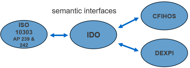
Figure 5 shows the selected information models. The task was to develop modelling patterns using the Industrial Data Ontology (IDO) to interconnect major standardised information models such as Data Exchange in the Process Industry (DEXPI), Capital Facilities Information Handover Specification (CFIHOS), and Application Protocols 239 and 242 of ISO 10303 (STEP: STandard for the Exchange of Product model data).
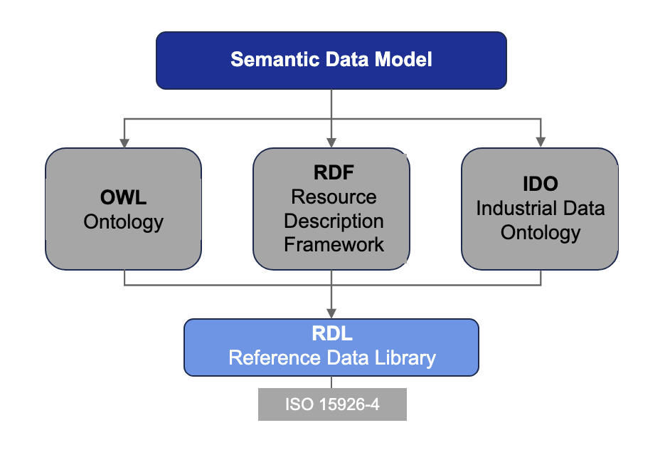
IDO, developed by the PCA community, is a W3C OWL ontology designed to cover all phases of the lifecycle of industrial assets and processes. It is currently being developed into ISO 23726-3. A detailed treatment of IDO’s architecture and property modelling framework is given in Handbook. The Resource Description Framework (RDF) and the Web Ontology Language (OWL) are foundational W3C specifications used to formally define such semantic models (see Figure 6).
While OWL, RDF, and IDO can be applied in many industries, process industry models require domain-specific Reference Data Libraries (RDLs) such as ISO 15926-4 to ensure unique, standardised definitions for classes and properties.
CFIHOS is an industry-wide initiative that aims to standardize the exchange of information between stakeholders involved in constructing, operating and maintaining industrial facilities. It aims to create a common language for structured handover across the asset lifecycle.
Initially, CFIHOS focused on the handover of structured data and documents from EPC(M) contractors to asset owners/operators at the end of a project. The long-term goal, however, is to provide a unified information model that supports the entire lifecycle, from vendor data acquisition to decommissioning.
At the core of CFIHOS is the Reference Data Library (RDL), which has a strong link to ISO 15926, part 4. This provides a standardized vocabulary and classification system for functional objects, documents, disciplines, and attributes. The CFIHOS RDL includes:
-
A list of classes for tags and physical equipment, defining what the asset should do and what it is.
-
a list of properties, including technical characteristics, measures and metadata.
-
Requirements by class: which attributes and documents are required for a given class.
-
standard coding systems to support integration into digital workflows.
-
A list of document types for each lifecycle stage.
-
A list of disciplines, such as mechanical, E&I and process engineering.
More information about CFIHOS is available on its official website: https://www.jip36-cfihos.org/cfihos-standards/.
Based on the results of the fPVN, a semantic CFIHOS concept was developed. The corresponding interconnection to IDO is detailed in document [1]. A broader treatment of CFIHOS alignment is given in Handbook > Alignment with CFIHOS.
ISO 10303-239 specifies the application protocol for product life cycle support.
The following are within the scope of ISO 10303-239:
-
information for defining a complex product and its support solution,
-
information required to maintain a complex product,
-
information required for through life configuration change management of a product and its support solution,
-
the representation of product assemblies,
-
the representation of a product through life,
-
the specification and planning of activities for a product,
-
the representation of the activity history of a product and
-
the representation of the product history.
ISO 10303-242 specifies the application protocol for Managed model based 3d engineering.
The following are within the scope of ISO 10303-242:
-
products of automotive, aerospace and other mechanical manufacturers and of their suppliers, including parts, assemblies of parts, tools, assemblies of tools, and raw materials,
-
engineering and product data for the purpose of long-term archiving and retrieval,
-
product data management,
-
process planning,
-
mechanical design,
-
message,
-
interface,
-
mating,
-
kinematics,
-
analysis management,
-
composite design,
-
electrical harness assembly design,
-
additive manufacturing part design and
-
requirements management.
More information about these application protocols is available on the website https://www.iso.org/standards.html.
This interconnection concept, describing how STEP and DEXPI could interoperate with IDO, is published in document [2]. A broader treatment of STEP alignment is given in Handbook > Alignment with ISO 10303 (STEP).
In Pump life cycle story a use case Pump Life Cycle Story is introduced. This use case is based on DEXPI specifications, which are described in General purpose of DEXPI.
The use case is also registered within the IDO project.
Notation Conventions¶
To ensure clarity and consistency throughout this document, specific notation conventions are applied when referring to elements from different information models:
-
Classes and properties defined in DEXPI are written in CamelCase.
-
Classes originating from ISO 15926 are written in CAPITALS. In accordance with OWL naming constraints, blank spaces in class and property names are replaced with underscores (_).
These conventions are intended to clearly distinguish between modelling sources and to avoid ambiguity in semantic representations.
General purpose of DEXPI¶
The aim of the DEXPI e.V. association is to develop and promote common data exchange standards for the process industry, covering all phases of the process plant life cycle, from the specification of functional requirements to the assets in service. The first focus of the DEXPI – Data Exchange in the Process Industry - was on the exchange of piping and instrumentation diagrams. The developed specification is called DEXPI Plant, and the first release appeared in 2016. A next focus of DEXPI was on block flow and process flow diagrams. A specification named DEXPI Process was designed and published. In 2025, DEXPI Release 2.0 was published. It covers both specifications. DEXPI specifications are always based on international standards.
Besides its own specifications, the DEXPI initiative has another important field of activity: networking with other organizations and initiatives to get a complete and aligned landscape of specifications and data standards for the asset life cycle of the process industry.
DEXPI specifications are provided by the DEXPI Initiative under the terms of the Creative Commons Attribution 4.0 International License (CC BY 4.0).
DEXPI Process and Plant use the standard ISO 15926 part 4 as reference data library for class and property definitions. Some additional classes and properties which were not covered by ISO 15926 part 4 are defined in the DEXPI sandbox https://sandbox.dexpi.org/#on-site-navigation as electronic inserts.
The home page of DEXPI e.V. www.dexpi.org offers a lot of information for the process industry community, e.g. the specification as pdf or html.
https://dexpi.org/wp-content/uploads/2025/10/DEXPI_Specification_2.0.pdf or
https://dexpi.gitlab.io/-/Specification/-/jobs/11676485644/artifacts/src/.build/html/html/index.html.
Another important document defines a process industry best practice for managing structured engineering and operational information across the entire asset lifecycle — from early concept development through engineering, construction, commissioning, and long-term plant operation.
General concept of DEXPI Plant¶
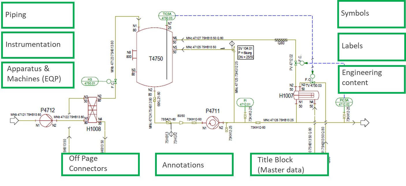
The DEXPI plant model in DEXPI 2.0 (former DEXPI Standard 1.4) was developed to facilitate the exchange of information between software tools in the form of a P&I D. Digitising the piping and instrumentation diagram creates a machine-readable plant topology, serving as a central information model for basic engineering. The elements shown in the DEXPI Standard 2.0 plant model are presented in Figure 7. The DEXPI Plant Information Model describes the plant’s structure and topology, i.e. the interaction between objects, such as the connection between a pipe and an apparatus. Typical symbols and labels are also included, but not as leading information. The purpose of DEXPI Plant is not to be a new P&I D standard. As a data-driven exchange standard, it aims to cover:
-
the different existing international, regional or company internal standards of P&I Ds,
-
P&I Ds of the different engineering phases,
-
draft and released P&I Ds and
-
a large variety of use cases.
DEXPI Plant was modelled with UML, and the first releases used the Proteus P&I D Profile Schema 4.0.1 as serialization platform. In 2016 DEXPI Plant 1.1, in 2017 DEXPI Plant 1.2 and in 2021 DEXPI Plant 1.3 was released. How DEXPI Plant 1.3 uses the Proteus schema is documented in the specification guide DEXPI-PID-Specification-1.3.pdf. The serialization of DEXPI 2.0 is done with XML.
The piping and instrumentation diagram (P&I D) is a central information carrier. In former days it was handled as a CAD document, nowadays it is an important part of many CAE systems. The P&I D is important for both main life cycle phases of the process industry: engineering and operating. It covers the objects of process plants for the three disciplines apparatuses & machines, piping and instrumentation. Some P&I Ds contain additional objects from other disciplines as well.
DEXPI Plant is based on international standards wherever possible:
-
Plant structure: ISO 10209,
-
Apparatuses/machines taxonomy and symbols: ISO 10628,
-
Piping taxonomy and symbols: ISO 10628,
-
Instrumentation concept: IEC 62424 / IEC 61987,
-
Boundary and maintainable item concepts: ISO 14224 and
-
Reference data library: ISO 15926 part 4.
DEXPI Plant does not have a very detailed property concept for the different classes. It only includes a few properties, for example:
-
required services,
-
design sizes,
-
design pressures,
-
design temperatures and
-
the required material.
General concept of DEXPI Process¶
DEXPI Process is a proposed standard for modelling information about process design, as it is presented on block flow and process flow diagrams. It was developed by the DEXPI+ working group and builds upon the DEXPI standard for piping and instrumentation diagrams. Digitalization is making increasing demands on the exchange of information in the process facility life cycle. Industry 4.0 methods require shared terminology and knowledge models to exchange information.
Standards and initiatives, such as, CFIHOS and DEXPI, try to address this need. All these focus on the physical plant items, as shown on a P&I D or 3D model. There is a lack of standards for early-phase, top-down process design. DEXPI Process fills this gap.
Like DEXPI Plant, UML was used to document the data modelling results for processes, as they are shown on block flow and process flow diagrams. As data-driven standard, DEXPI Process covers unit operations, streams and instrumentation activities. Symbols and labels are handled as lower-ranking information. ISO 15926 part 4 is also used as a reference data library.
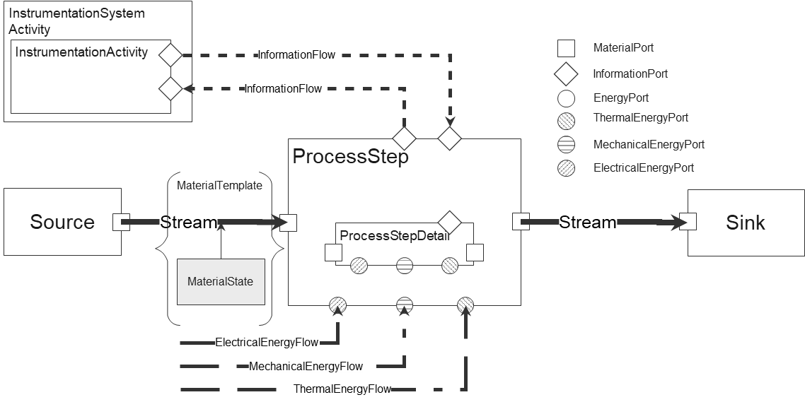
The DEXPI process data model is shown in Figure 8. This illustrates the primary classes within the model and their relationships. The model comprises:
-
Process steps and unit operations (activities)
-
All the itemised activities (process steps and unit operations) required to run the process, along with their respective classes.
-
The name of each activity, to explain its function (e.g. Distillation 1).
-
Process step details and characteristic design values of process units.
-
Streams
-
Numbering of all streams.
-
All material streams entering and leaving the unit, as well as between activities, are shown as main flow lines according to ISO 10628, with process data such as pressure, temperature and mass flow.
-
The electrical and thermal energy flow exchanged with the process steps.
-
Identification of all fluids and solids entering or leaving the process, as well as sources and sinks.
-
All required basic process controls.
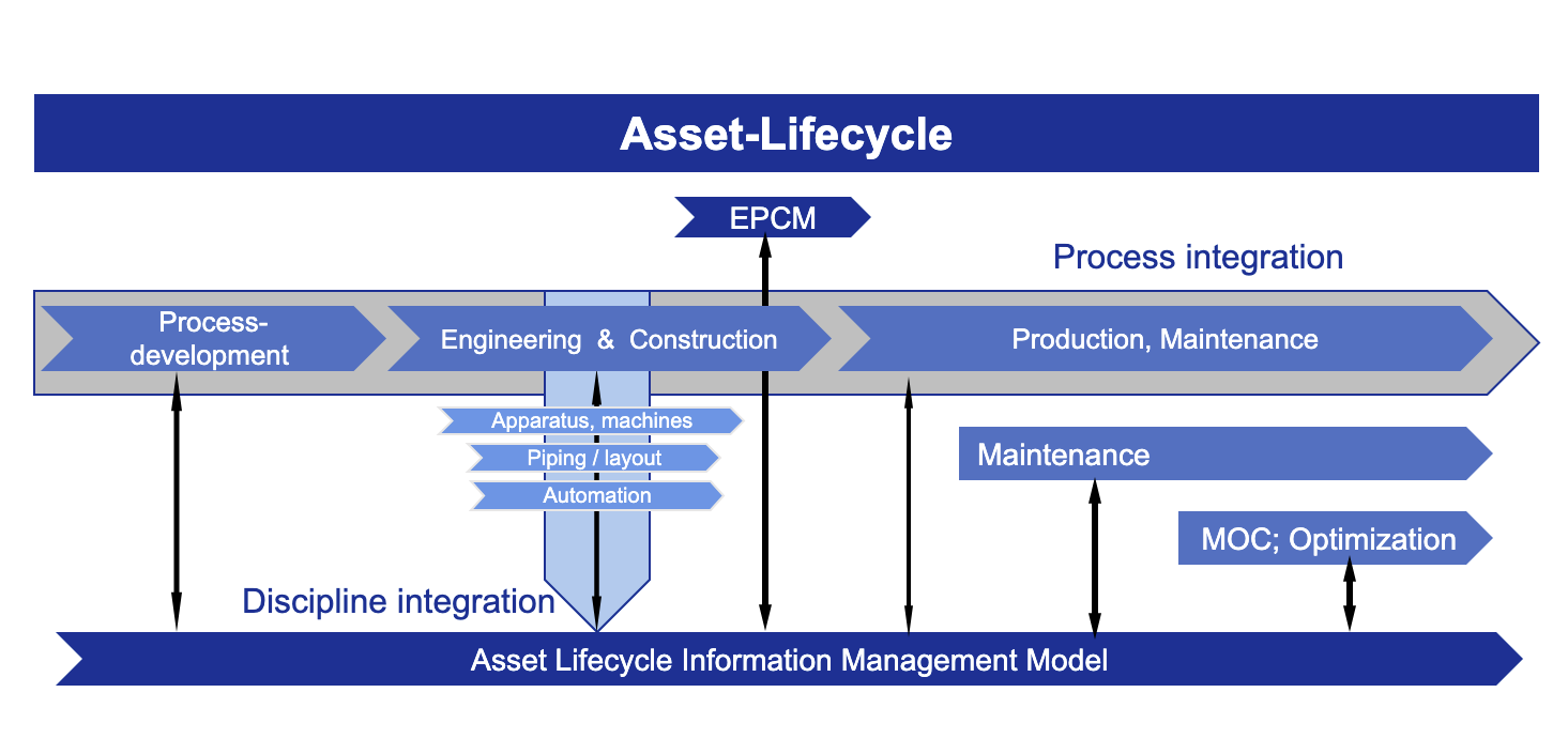
Life cycle view of the Process Industry¶
A generally accepted understanding exists regarding the different processes of the plant life cycle of the process industry. Even the names for the different processes are very similar. Figure 9 shows a simplified example.
To support the different processes in a digital manner, appropriate information structures are required. The approaches for the information structures can be described from different but complementary perspectives. While standards such as ISO 15926 provide a highly detailed lifecycle breakdown, industrial initiatives like DEXPI and CFIHOS structure lifecycle information around process, plant, and asset views. This chapter compares and aligns these approaches. In the project Energieeffizienzsteigerung Prozessindustrie (ENPRO) Figure 10 was developed. This project was funded by the German government.
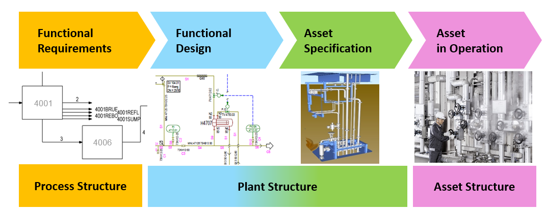
Functional requirements define what the chemical/physical process should achieve and are typically represented by unit operations and streams. Historically, chemical processes were visualised by using block flow diagrams (BFDs) and process flow diagrams (PFDs).
The functional design, i.e. the plant structure and initial tag specification, is covered by the plant model. This is traditionally visualised using a piping and instrumentation diagram (P&I D) and a 3D model. Asset specifications were developed to buy the necessary devices. The plant will be constructed with the delivered devices. These assets enable and support plant operation. There are three main information structures to serve the processes of an owner/operator or involved engineering companies: the process, specified plant and asset structure. Each structure contains its own set of objects, while the relations between these objects document the requirement and realization chain across lifecycle stages.
Based on the Life cycle stages model from ISO 15926, which is very detailed, a common aligned picture with the ENPRO result was designed (Figure 11). There is only one additional information structure present. Device vendors have their own view on their products. First, they offer device types and then they deliver their products. These products are integrated into the overall plant and instantiated by the owner/operator as assets. Each asset is linked to its corresponding plant item through a temporal relationship.
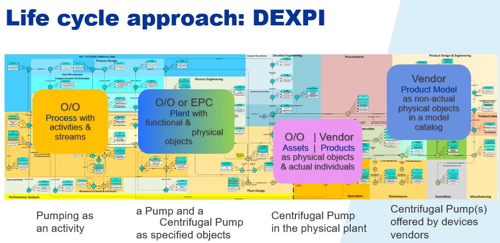
The typical pump example is used to explain this approach a little bit more in detail. During the process design the PROCESS with its PROCESS_STEPs, the UNIT_OPERATIONs like PUMPING and the PROCESS_STREAMs are developed, calculated, and designed. The results were documented on block and process flow diagrams. DEXPI used the colour orange for this part of the life cycle. The DEXPI Process specification covers the results.
One of the first engineering tasks is to setup the PROCESS_PLANT design based on the process design results. E.g. one or more PUMP_SYSTEMs could be designed for the ACTIVITY_PUMPING. Process data sheets cover the results for the specified PUMPs. The topology of the PROCESS_PLANT will be specified by a first issue of a P&I D. DEXPI uses the colour blue for this part of the life cycle.
A task of basic and/or detail engineering is the technical design of the functional PROCESS_PLANT items. In modelling language it is expressed as: PUMPS will be subclassified as e.g. CENTRIFUGAL_PUMPs. Follow up releases of the first P&I D were created as well. The DEXPI Plant specification covers this design step. For these PLANT items technical specification documents were created, the 3D layout model as well. DEXPI uses the colour green for this part of the life cycle.
Procurement has the task to buy the specified devices and have a look at the PRODUCT market. Device manufacturers offer device types, which should fulfil the requirements. After a technical and financial check the devices are bought and delivered as individuals to the owner/operation or EPC. They were constructed and installed as ASSETs. The ASSETs get a temporal relationship to their PLANT items. DEXPI uses the colour pale blue for the PRODUCTs and purple for the Assets.
CFIHOS has a similar approach in its information model. Only the terms differ a little bit (Figure 12). The plant items are called tags and the assets called equipments.
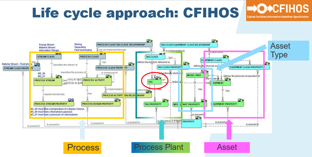
These three approaches introduced above are aligned.
Another approach often used for power plants is available as ISO/IEC 81346. ISO/IEC 81346 is an international standard that provides a framework for structuring and referencing industrial systems, installations, and equipment. Part 1 introduces the concept of aspects, especially the aspects of
-
function,
-
product and
-
location.
This aspect view is quite helpful, but the alignment of the ISO/IEC 81346 with the other standards is still under discussion. If the aspects are used and extended as the University of Oslo proposed, an alignment is achieved with the other standards (Figure 13).
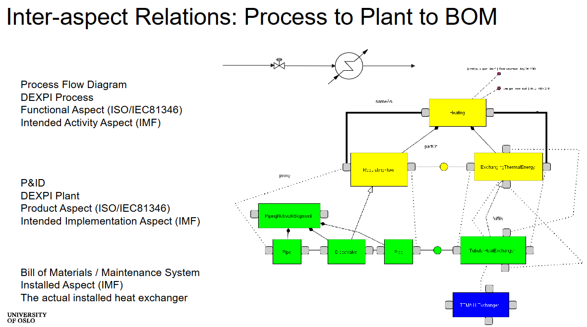
In recent years, digitalization in civil, structural, and architectural engineering has progressed rapidly. Many new Building Information Modelling (BIM) standards have been developed. In the standard EN 17632 there is an important life cycle approach (Figure 14).
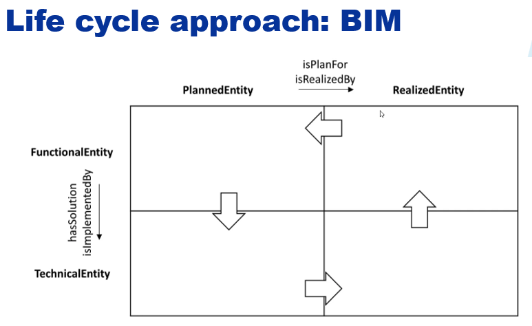
Four parts are built with two vertical assignments (PlannedEntity and RealizedEntity) and two horizontal assignments (FunctionalEntity and TechnicalEntity).
Adding an information structure (e.g. measurement and production data) for running plants the approach of the process industry can be aligned with the BIM approach (Figure 15). This figure contains additional modelling concepts for the IDO mapping. They are introduced in Modelling pattern with IDO general solutions.
FunctionalEntities are present in two different information structures: process and specified plant. Therefore the specified plant structure looms into the upper left quadrant.
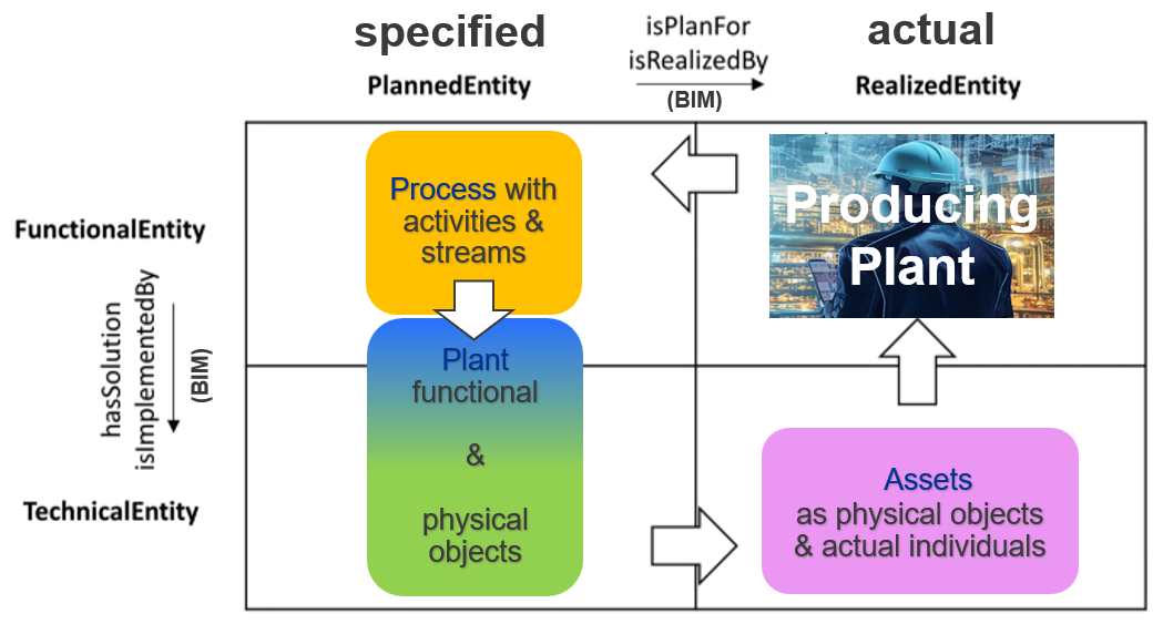
Figure 16 is the representation of the same concepts as in Figure 15 shown. Now the V-Model diagram is used. In this representation, verification is performed at the TechnicalEntity level, whereas validation occurs at the FunctionalEntity level.
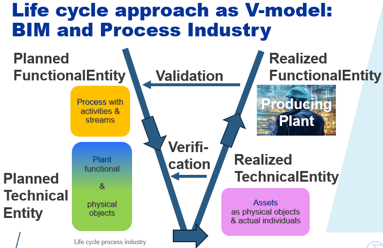
Pump life cycle story¶
The typical pump example is used to explain the main information structures of the life cycle. It uses DEXPI classes, which have a 1:1 mapping to ISO 15926 Part 4 classes. In this example, all object identifiers have exactly five characters. This is a design decision for naming, only to make it more readable.
Information structure for process design¶
The example contains one ProcessStep PST01. It is part of the overall Process PR001. Figure 17 shows some results of the process design. The upper part shows a block flow diagram. The lower part shows a process flow diagram. Both diagrams show the same content:
-
a StoringMaterial UnitOperation UO001 with a fluid outlet MaterialPort OP001,
-
a Pumping UnitOperation UO002 with a fluid inlet MaterialPort IP001 and fluid outlet MaterialPort OP001,
-
a ReactingChemicals UnitOperation UO003 with a fluid inlet MaterialPort IP001,
-
two Stream(s) PS001 und PS002, with
-
PS001 connecting UO001 with UO002 and
-
PS002 connecting UO002 with UO003.
UO002 has one property. The DifferentialPressure between the inlet port IP001 and the outlet port OP001 shall be 10 bar, a value which is valid under the condition “Absolute Pressure”.
The DEXPI process module is an information model which covers the results of the process design. In the life cycle stages model Figure 11, the process structure is shown in orange.
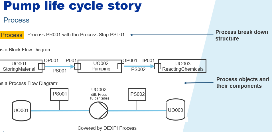
Information structure for the design of a process plant¶
One of the first tasks during Front End Engineering and Design (FEED) is to set up the design of the ProcessPlant PP001 with its PlantSection PST01. This is based on the process design. A PumpSystem PPS01 is designed to fulfil the requirements of the Pumping UnitOperation UO002. The PumpSystem has the following parts:
-
a Pump P0001,
-
a Motor MP001 to drive the Pump P0001 and
-
a ProcessInstrumentationFunction VF001 to monitor the health of the Pump P0001 with its ProcessSignalGeneratingFunction VFM01.
Pump P0001 has the property DifferentialPressure with a value of 13.5 bar under the condition “Absolute Pressure”.
P0001 has a ProcessNozzle I0001 to take over the task of the inlet MaterialPort IP001.
One Vessel V0001 will fulfil the task of UnitOperation UO001, another Vessel V0002 the task of UO003.
The PipingNetworkSystem(s) L0001 and L0002 are designed as container for the Stream(s) PS001 and PS002. All other process objects will get their specified functional objects as the process plant matching parts.
In the life cycle stages model Figure 11, the plant design structure is shown in blue.
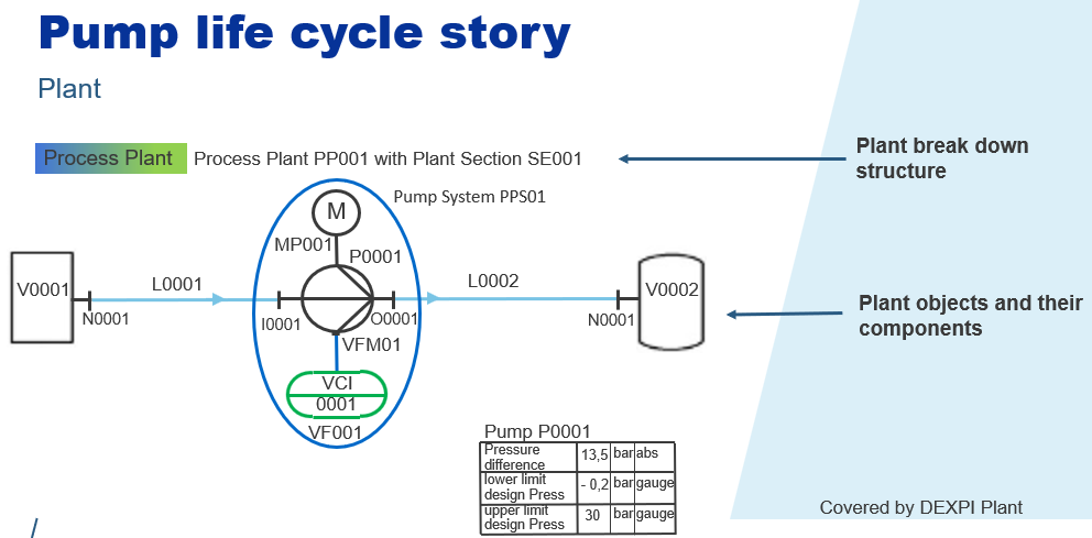
Basic and detailed engineering define the technical design of the functional plant items. In the life cycle stages model Figure 11, this design structure is shown in green. The DEXPI plant module is an information model which covers the FEED, the basic and detailed engineering results as well. Figure 18 shows the design results of the pump example as a P&I D.
The parts of the PumpSystem PS001 got their technical design:
-
the Pump P0001 is specialized as CentrifugalPump,
-
the Motor MP001 is specialized as an AlternatingCurrentMotor, and
-
a MeasuringSystem VS001 is designed to do the task of the SignalGeneratingFunction VFM01.
-
CentrifugalPump P0001 has additional technical properties:
-
LowerLimitDesignPressure: –0.2 bar
-
UpperLimitDesignPressure: 30 bar.
Both values are defined as quantities with the unit of measure “bar” and are valid under the condition “GaugePressure”.
The Vessel V0001 is specialized as Tank, V0002 as PressureVessel.
The PipingNetworkSystem(S) L0001 and L0002 will receive additional mechanical data (out of scope).
Information structure for the actual process plant¶
Procurement reviews the product market and purchases the specified devices. After construction, the plant becomes the actual Process Plant PP001.
In this example:
-
A CentrifugalPump with serial number 47110 is purchased from manufacturing organization ABCDE.
-
It is installed at its physical location.
-
It receives equipment number 12345 in the asset register.
-
This asset is related to the specified plant item P0001.
-
The actual CentrifugalPump (equipment number 12345, serial number 47110) has:
-
LowerLimitDesignPressure: –0.5 bar and
-
UpperLimitDesignPressure: 35 bar.
-
Both values use the unit “bar” and are valid under the condition “GaugePressure”.
-
-
A MeasuringSystem with serial number 47111 is purchased from manufacturing organization ABCDF.
-
It is installed and receives equipment number 12346.
-
This asset is related to the specified plant item VS001.
-
An AlternatingCurrentMotor with serial number 47112 is purchased from manufacturing organization ABCDG.
-
It is installed and receives equipment number 12347.
-
This asset is related to the specified plant item MP001.
These processes and information structures are outside the scope of the DEXPI Process and Plant modules. However, the asset structure and its relation to the specified Process Plant should be included in the IDO mapping. In the life cycle stages model Figure 11 the asset structure is shown in purple and the product structure in light blue.
Modelling pattern with IDO general solutions¶
The pump life cycle story described above is based on DEXPI Process and Plant specifications together with additional asset information. The example is documented in an XML file, which is included in the Appendix.
The first two parts of the XML file contain information about the process and the specified plant. These parts could be generated by a DEXPI export. The remaining two parts — the assets and the relations between the first three parts — are not covered by DEXPI. Therefore, the file was compiled completely by hand.
Namespaces are used to separate the different parts. To ensure the uniqueness of the different objects within their scopes, the XML nodes were given an additional prefix: dexpipro for the process scope, dexpipla for the specified plant scope, and dexpiass for the asset scope.
Based on this XML file, Turtle files can be generated, one for each ontology. In this case study, the Turtle files for the ontologies were also compiled manually, verified by tools like GraphDB and Protégé. A layered ontology structure is used, as shown in Figure 19.
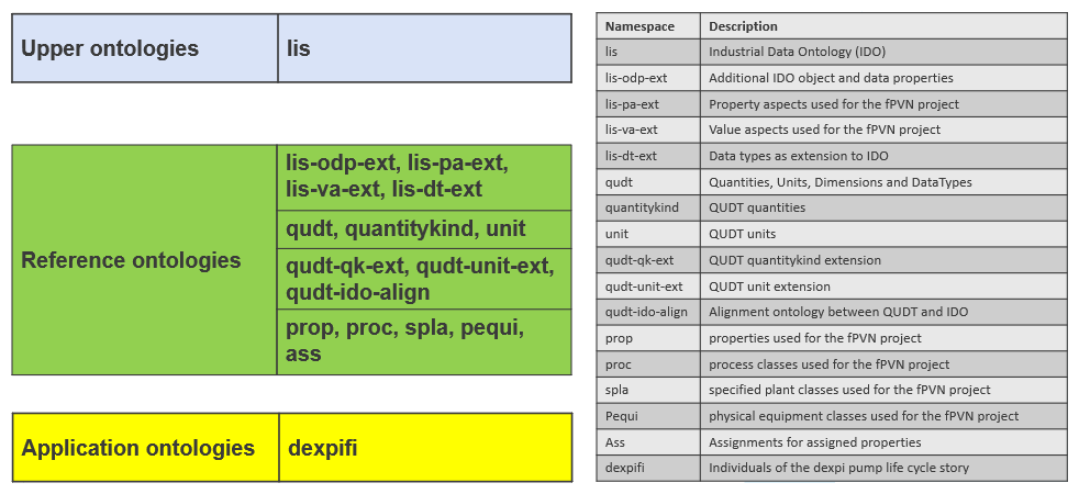
IDO represents the upper-level ontologies. When modelling the pump life cycle story with this ontology together with OWL, RDF, and RDFS some gaps remain. These gaps are addressed by modelling additional concepts in the lis-odp-ext ontology. Future releases of IDO could potentially integrate these specifications.
The IDO PLMs Process, Equipment, and UoM are not used because they are incomplete and currently not maintained. Instead, QUDT is used for the unit-of-measurement concepts, and ISO 15926 Part 4 is used as the reference data library.
The lis-odp-ext, lis-pa-ext, lis-va-ext, and lis-dt-ext ontologies, together with the prop ontology for the properties and ass ontology for property assignments; proc, spla and, pequi for the class definitions; and dexpifi ontology for the instances representing the pump life cycle story, constitutes the main result of this use case. The corresponding Turtle files follow the design principles defined in the PCA Host Content Requirements, which are available on the PCA service website. The Turtle files for the use case are provided in Turtle files for the use case. They can be loaded into tools like GraphDB or Protégé. The ontologies prop, proc, spla, pequi, and ass are on domain level, not only valid for DEXPI.
To manage the information properly, namespaces and prefixes for class names are used.
The prefixes specified_ and actual_ are used to distinguish between classes representing the specified process plant and the actual plant. CFIHOS, STEP, and DEXPI define this common requirement because the classes for specified and actual plants will have different property sets (see Handbook > The three-world model).
Property Concept¶
The property decomposition concept [3], compiled during the fPVN project, is a major source for this specification. The conceptual framework and property typology are described in Handbook > Methodology; the unified reification model in Handbook > Unified property reification model.
At the class level, allowable properties are assigned to each class. Identification properties are restricted using owl:qualifiedCardinality, ensuring that exactly one value must be provided. Other properties are restricted using owl:maxQualifiedCardinality 1, meaning that at most one value may be assigned. N-ary relations are not considered in this property model.
Instances of classes obtain their possible properties through their class relationships. Properties defined with owl:maxQualifiedCardinality 1 can be assigned to instances at most once. If such a property is assigned, it may either have a value or remain unspecified (i.e., no value is provided).
One result of the fPVN work package is the requirement to distinguish at least five types of properties:
-
Identification
-
Physical Quantity
-
Classification
-
Referencing
-
Description (single-language or multi-language).
These property types are defined as classes in the prop ontology. The properties used should reference the corresponding entries defined in ISO 15926-4.
For physical quantity properties, the class definition shall reference a QuantityKind defined in QUDT.
At the instance level, the unit of measure (UoM) shall be assigned using qudt:unit provided by QUDT. Physical quantities with the QuantityKind Pressure shall additionally be classified as either PressureGauge or PressureAbsolute. To enable the use of QUDT, some additional ontologies were required. The definition of physical quantity properties is based on five aspects:
-
Place
-
Range
-
Origin
-
Scope
-
Context.
These aspects and their possible values, are defined within the lis-pa-ext and lis-va-ext ontolo-gies as classes and subclasses. They may be used as part of the formal definition of physical quantity properties and their value assignments.
IDO requires the differentiation between dependent and assigned properties. Dependent entities are those that rely on other entities for their existence or properties. lis:Quality is a subclass of dependent in the IDO model. Its entities denote inherent attributes present whenever their bearer exists. Assigned properties are supported by IDO within the Object → InformationObject modelling branch.
Modelling pattern for the DEXPI process part¶
Table 4 lists the classes required to represent the process part of the pump life cycle story. Target and Source represent relations in the DEXPI model. They indirectly contain information about the function of the port.
| part 4 | DEXPI class | proc: | IDO |
|---|---|---|---|
| PROCESS | Process | Process | Activity |
| PROCESS STEP | ProcessStep | ProcessStep | Activity |
| UNIT OPERATION | UnitOperation | UnitOperation | Activity |
| PUMPING | Pumping | Pumping | Activity |
| CHEMICAL REACTING | ReactingChemicals | ReactingChemicals | Activity |
| STORING | StoringMaterial | StoringMaterial | Activity |
| PORT | Port | Port | Activity |
| PORT(transport) | MaterialPort | MaterialPort | Activity |
| INLET PORT | „Target“ | Activity | |
| OUTLET PORT | „Source“ | Activity | |
| Stream | ProcessConnection | ProcessConnection | Activity |
| PROCESS STREAM | Stream | Stream | Activity |
All classes were modelled as lis:Activity to represent the process uniformly as an activity-based structure. This enables consistent handling. The block flow diagram and the process flow diagram are represented entirely as activity diagrams.
However, IDO cannot represent certain dependency concepts between PROCESS_STREAMs, Ports, and UNIT_OPERATIONS. This gap was closed by introducing additional object properties (feeds and deliversTo) in the lis-odp-ext ontology.
Figure 20 shows the use of the ontology hierarchy (see Figure 19) for the process part.
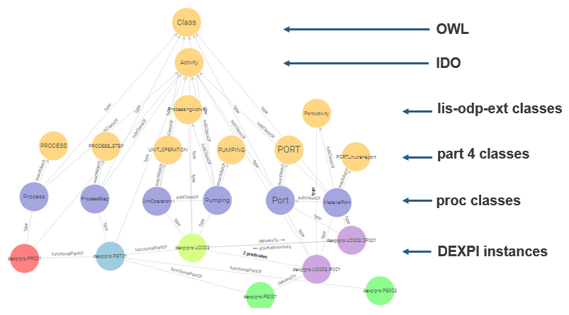
Table 5 contains example properties. For the property DifferentialPressure a detailed modelling pattern will be introduced. There is still an open discussion about dependent properties: Can specified objects have dependent properties?
| class | property | cardinality | IDO property type |
|---|---|---|---|
| Process | Identifier | 1 | assigned |
| ProcessStep | Identifier | 1 | assigned |
| UnitOperation | Identifier | 1 | assigned |
| Pumping | DifferentialPressure | 0..1 | dependent |
| ReactingChemicals | |||
| StoringMaterial | |||
| Port | Identifier | 1 | assigned |
| MaterialPort | |||
| ProcessConnection | Identifier | 1 | assigned |
| Stream |
Process break down structure¶
Figure 21 shows the modelling pattern for the typical process breakdown structure:
Process → ProcessStep → UnitOperation (e.g., Pumping).
Yellow boxes represent instances, blue boxes represent DEXPI classes, green boxes represent ISO 15926 Part 4 classes, pale gray boxes represent the lis-odp-ext classes, and gray boxes represent the IDO classes. This modelling pattern covers both the class level and the instance example of the pump life cycle story.
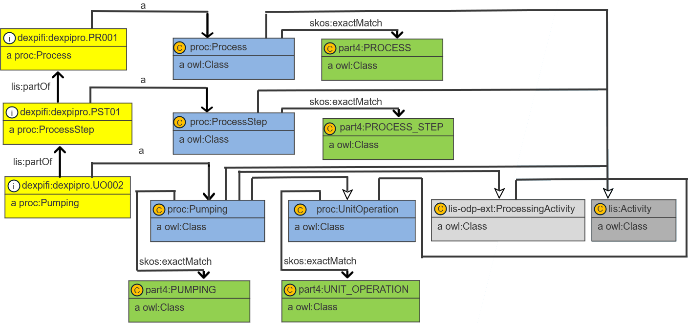
Pumping modelling pattern¶
Another modelling pattern was developed for the Pumping instance UO002. The coloured boxes are used in the same way as in Figure 21.
At the instance level, the additional object properties of the lis-odp-ext ontology support process connectivity: lis-odp-ext:feeds and lis-odp-ext:deliversTo.
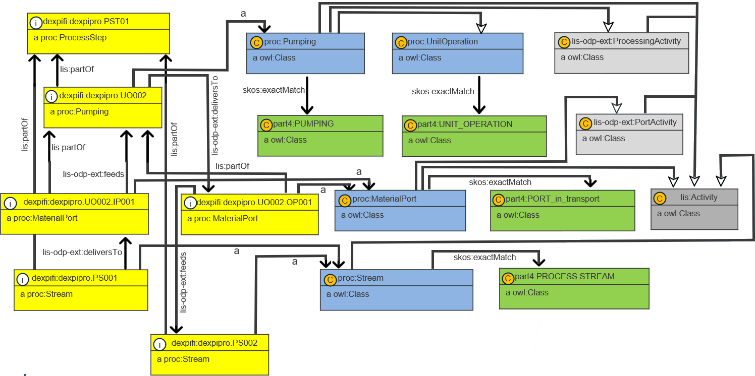
Physical quantity property modelling pattern: differential pressure¶
It is not possible to assign properties directly to lis:Activity classes. A bridge with lis:ActivityProfile is required. Using this bridge the modelling pattern DifferentialPressure of the Pumping object UO002 is nearly the same as the pattern DifferentialPressure of the specified_Pump P0001 (Figure 24, Figure 25).
Modelling pattern for the specified process plant part¶
Table 6 contains the classes required to represent the specified process plant portion of the pump life-cycle story. The Part 4 and DEXPI classes used cover a broader scope than the specified process plant itself, as they are also intended to represent the actual process plant.
To establish a clear mapping to IDO and to better support the life-cycle concept, additional specific subclasses are required. Therefore, all DEXPI classes listed in Table 6 were extended by subclasses using the prefix specified_ in the XML and Turtle files.
The functional DEXPI classes (shown in blue in Figure 11) are classified in IDO as a System, whereas the physical classes (shown in green in Figure 11) are classified as InanimatePhysicalObject.
At the instance level, an additional object property from the lis-odp-ext ontology is used to relate specified functional objects to their corresponding specified physical objects: lis-odp-ext:specifiedTechnicalBy, with its inverse lis-odp-ext:specifiesTechnical. This object property is used, for example, to relate a specified_ProcessSignalGeneratingFunction to a MeasuringSystem.
| part 4 | DEXPI class | spla: |
IDO |
|---|---|---|---|
| PROCESS PLANT | ProcessPlant | specified_ProcessPlant | System |
| PLANT SECTION | PlantSection | specified_PlantSection | System |
| PUMP SYSTEM | System | specified_System | System |
| PUMP | Pump | specified_Pump | System |
| CENTRIFUGAL PUMP | CentrifugalPump | specified_CentrifugalPump | InanimatePhysicalObject |
| PROCESS NOZZLE | ProcessNozzle | specified_ProcessNozzle | InanimatePhysicalObject |
| PIPING NETWORK SYSTEM | PipingNetworkSystem | specified_PipingNetworkSystem | System |
| ELECTRIC MOTOR | Motor | specified_Motor | System |
| ALTERNATING CURRENT MOTOR | AlternatingCurrentMotor | specified_AlternatingCurrentMotor | InanimatePhysicalObject |
| INSTRUMENTATION FUNCTION | InstrumentationFunction | specified_InstrumentationFunction | System |
| PROCESS SIGNAL GENERATING FUNCTION | ProcessSignalGeneratingFunction | specified_ProcessSignalGeneratingFunction | System |
| MEASURING SYSTEM | MeasuringSystem | specified_MeasuringSystem | InanimatePhysicalObject |
| VESSEL | Vessel | specified_Vessel | System |
| TANK | Tank | specified_Tank | InanimatePhysicalObject |
| PRESSURIZED CONTAINER | PressureVessel | specified_PressureVessel | InanimatePhysicalObject |
Figure 23 shows the usage of the ontology hierarchy (see Figure 19) for the process part.
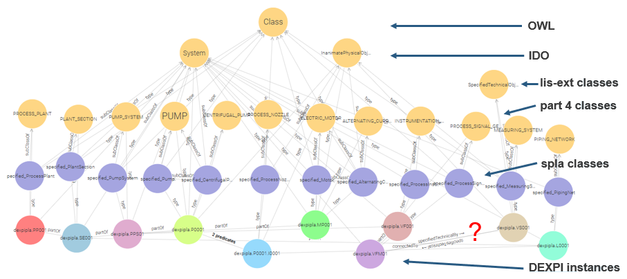
Note
The concept of lis-odp-ext:specifiesTechnical is still a proposal.
Table 7 contains examples of properties. For the properties Description, Identifier of specified_PlantSection, DifferentialPressure, and UpperLimitDesignPressure detailed modelling patterns will be introduced.
| class | Property examples | cardinality | IDO property type |
|---|---|---|---|
| specified_ProcessPlant | Identifier | 1 | assigned |
| Description | 0..1 | assigned | |
| specified_PlantSection | Identifier | 1 | assigned |
| specified_System | Identifier | 1 | assigned |
| specified_Pump | TagName | 1 | assigned |
| DifferentialPressure | 0..1 | dependent | |
| specified_CentrifugalPump | LowerLimitDesignPressure | 0..1 | dependent |
| UpperLimitDesignPressure | 0..1 | dependent | |
| specified_ProcessNozzle | SubTagName | 1 | assigned |
| specified_PipingNetworkSystem | LineNumber | 1 | assigned |
| specified_Motor | TagName | 1 | assigned |
| specified_AlternatingCurrentMotor | |||
| specified_InstrumentationFunction | ProcessInstrumentationFunctionNumber | 1 | assigned |
| specified_ProcessSignalGeneratingFunction | ProcessSignalGeneratingFunctionNumber | 1 | assigned |
| specified_MeasuringSystem | MeasuringSystemNumber | 1 | assigned |
| specified_Vessel | TagName | 1 | assigned |
| specified_Tank | |||
| specified_PressureVessel |
Physical quantity property pattern of a specified_Pump¶
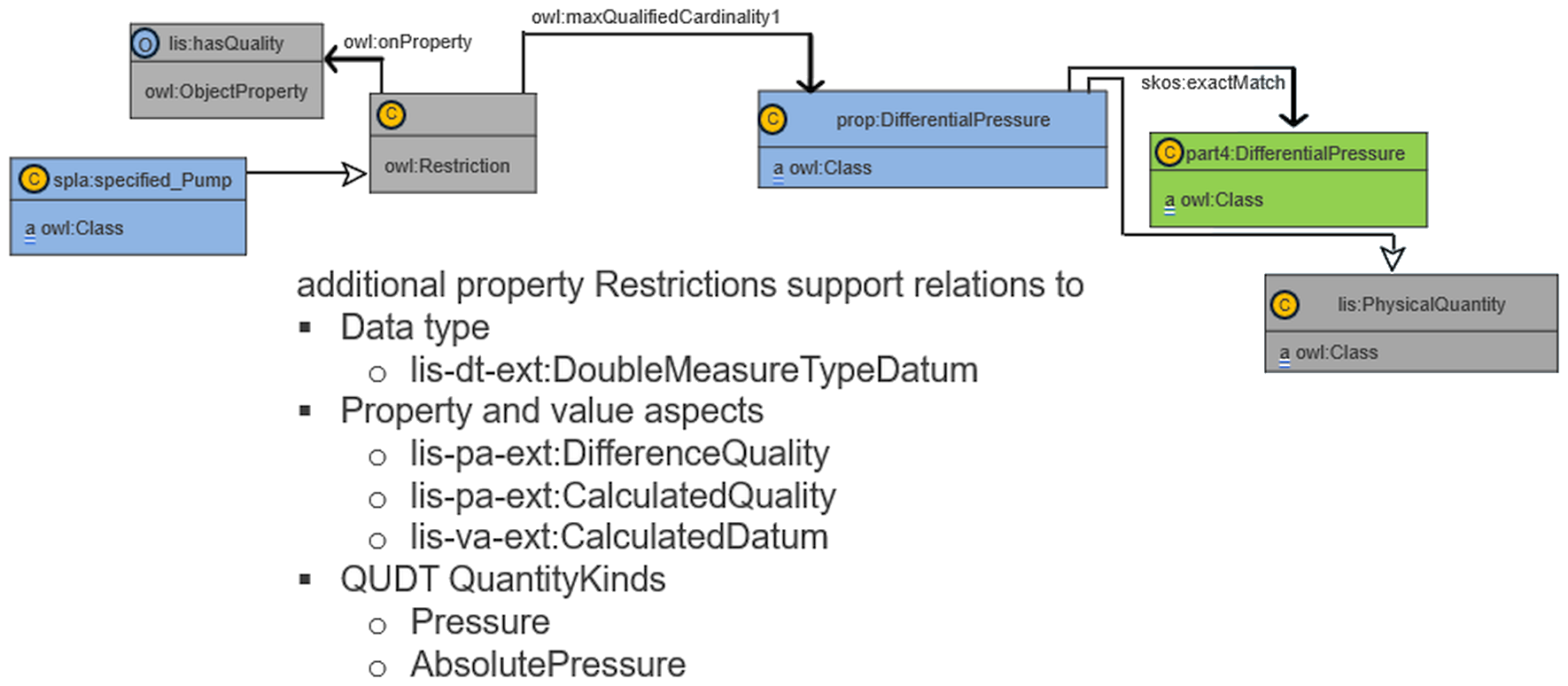
The property DifferentialPressure is defined as a dependent class and as a subclass of lis:PhysicalQuantity. It is assigned as permissible property of the class specified_Pump. Using an OWL restriction, the QUDT QuantityKind Pressure is assigned. The relations to the data type DoubleMeasureTypeDatum, the QUDT QuantityKind AbsolutePressure, and the property aspects DifferentialDatum and CalculatedDatum are supported with Restrictions (see Figure 24).
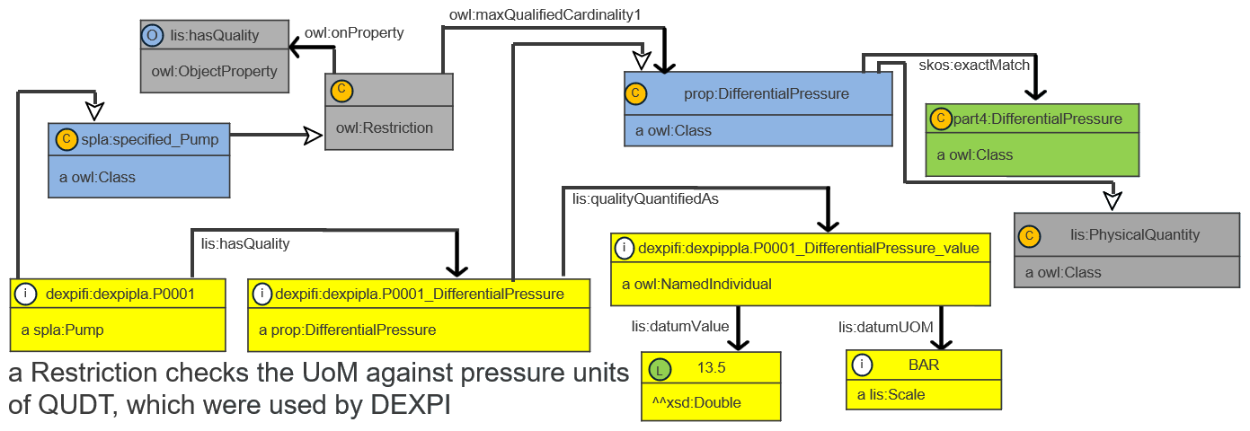
At the instances level (Figure 25) lis:hasQuality and lis:qualityQuantifiedAs are used to connect the typical IDO instance triple parts: bearer, property and value. The unit of measurement BAR as a unit of QUDT is used.
Identification property pattern of a specified_PlantSection¶
The property Identifier is modelled using the assigned concept. An initial modelling approach is shown in Figure 26.
First, the property is modelled as lis:InformationObject. Assigned properties require an assignment class, in this case, IdentifierAssignmentActivity. A Restriction ensures that exactly one Identifier can be assigned to a PlantSection.
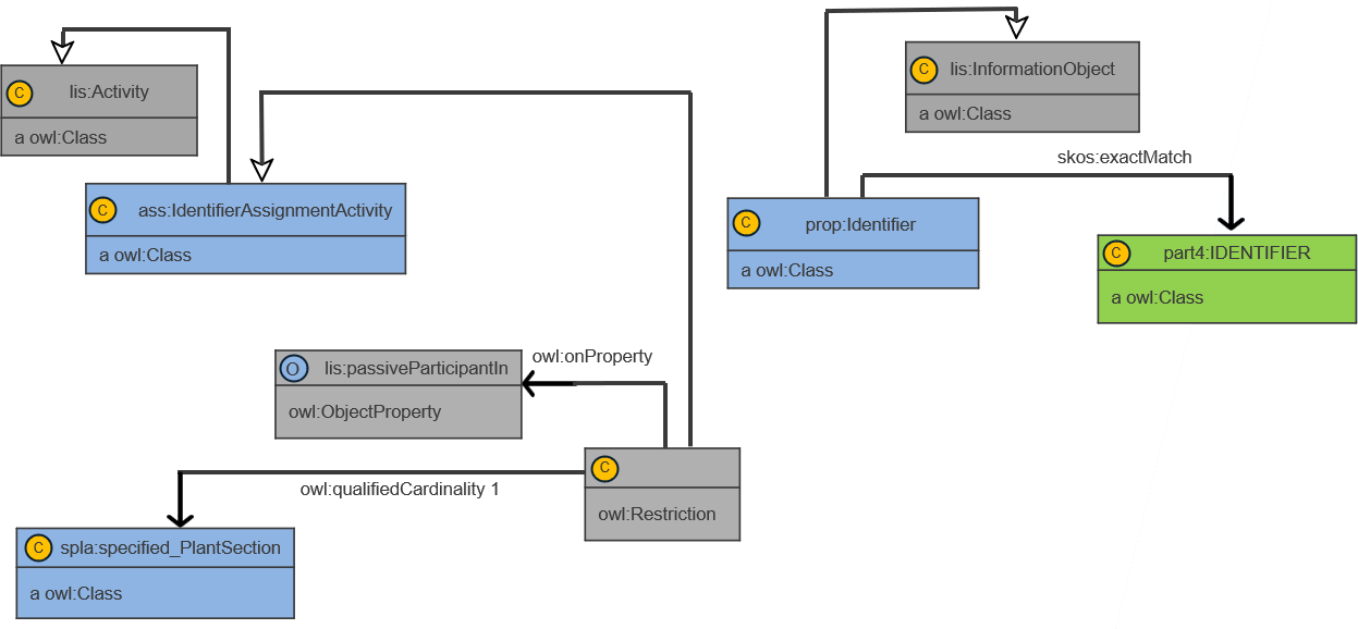
At the instance level (see Figure 27) the specified_PlantSection and the Identifier are assigned to each other via the ObjectProperty lis:hasPassiveParticipant.
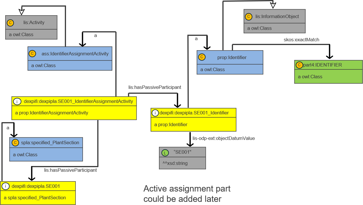
Description property pattern of a specified_ProcessPlant¶
The property Description is modelled using the assigned concept. This property can be used for different objects, like other properties. The modelling pattern is very similar to the pattern of the Identifier of the specified_PlantSection (Figure 26, Figure 27), only the cardinality (0..1) in the Restriction is different.
The definition is as follows:
prop:Description rdf:type owl:Class ;
    rdfs:label "Description"@en ;
    rdfs:comment "Description of an object."@en ;
    skos:exactMatch part4:DESCRIPTION ;
    rdfs:subClassOf lis:InformationObject .
The corresponding assignment class includes that Description is a permissible property of class specified_ProcessPlant:
ass:DescriptionAssignmentActivity rdf:type owl:Class ;
    rdfs:label "Description Assignment Activity" ;
    rdfs:comment "Assignment for the property Description."@en ;
    rdfs:subClassOf lis:Activity ;
    rdfs:subClassOf [
        a owl:Restriction ;
        owl:onProperty lis:hasPassiveParticipant ;
        owl:maxQualifiedCardinality "1"^^xsd:nonNegativeInteger ;
        owl:onClass spla:specified_ProcessPlant ] .
At the instance level the value of the Description is assigned to the instance dexpipla.PP001 of the class specified_ProcessPlant:
dexpifi:dexpipla.PP001_Description rdf:type prop:Description ;
    lis-odp-ext:objectDatumValue "I am the specified process plant of the pump life cycle story"^^xsd:string .

dexpifi:dexpipla.PP001_DescriptionAssignmentActivity rdf:type ass:DescriptionAssignmentActivity ;
    lis:hasPassiveParticipant dexpifi:dexpipla.PP001 ;
    lis:hasPassiveParticipant dexpifi:dexpipla.PP001_Description .
Pattern for UpperLimitDesignPressure¶
The modelling pattern for the property UpperLimitDesignPressure of a specified_CentrifugalPump uses the same principles as those applied to DifferentialPressure of a specified_Pump (Figure 24, Figure 25). There is, however, one significant difference: UpperLimitDesignPressure is modelled on two levels. First, DesignPressure is defined using the property aspects lis-pa-ext:SpecifiedDatum and lis-pa-ext:DesignDatum, together with the QUDT QuantityKind GaugePressure. UpperLimitDesignPressure inherits these definitions and is additionally assigned the value aspect lis-va-ext:UpperLimit.
IDO mapping for the asset information structure¶
Table 8 contains the classes required to represent the actual process plant portion of the pump life-cycle story. There is currently no DEXPI specification for this information structure. Therefore, Part 4 classes were used. However, these classes cover a broader scope than the actual process plant because they are also intended to represent the specified process plant.
To establish a clear mapping to IDO and to better support the life-cycle concept, additional specific subclasses were required. Therefore, all Part 4 classes listed in Table 8 were extended with subclasses using the prefix actual_ in the XML and Turtle files.
| part 4 | pequi: |
IDO |
|---|---|---|
| PROCESS PLANT | actual_ProcessPlant | InanimatePhysicalObject |
| PLANT SECTION | actual_PlantSection | InanimatePhysicalObject |
| CENTRIFUGAL PUMP | actual_CentrifugalPump | InanimatePhysicalObject |
| ALTERNATING CURRENT MOTOR | actual_AlternatingCurrentMotor | InanimatePhysicalObject |
| MEASURING SYSTEM | actual_MeasuringSystem | InanimatePhysicalObject |
All classes were modelled as lis:InanimatePhysicalObject(s).
Figure 28 shows the usage of the ontology hierarchy (see Figure 19) for the actual process plant part. This modelling approach is intentionally simple and does not include topology. The topology is instead represented through references from the actual plant objects to the corresponding specified plant objects.
For modelling the actual plant objects, the IDO vocabulary was sufficient to cover the requirements.
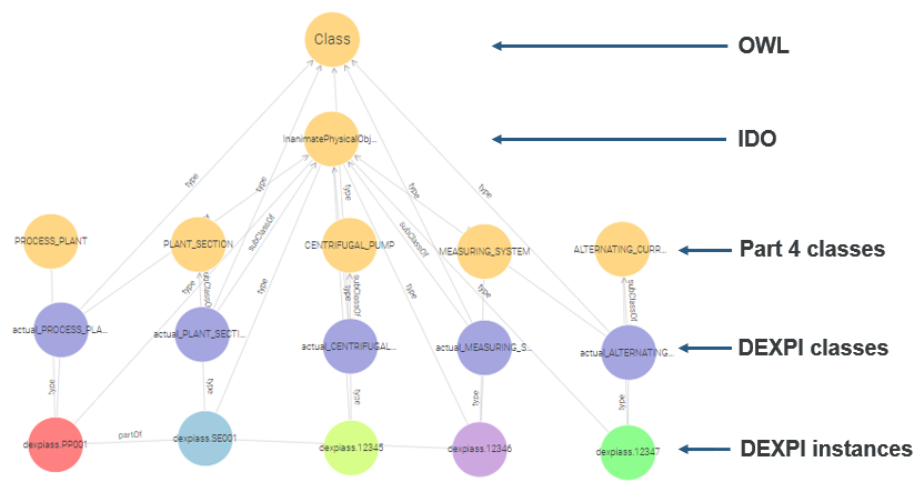
Table 9 contains the property examples. For the properties SerialNumber and UpperLimitDesignPressure detailed modelling patterns will be introduced.
| class | property | cardinality | IDO property type |
|---|---|---|---|
| actual_ProcessPlant | Identifier | 1 | assigned |
| actual_PlantSection | Identifier | 1 | assigned |
| actual_CentrifugalPump | EquipmentNumber | 1 | assigned |
| LowerLimitDesignPressure | 0..1 | dependent | |
| UpperLimitDesignPressure | 0..1 | dependent | |
| VendorNumber | 0..1 | assigned | |
| SerialNumber | 0..1 | assigned | |
| actual_AlternatingCurrentMotor | EquipmentNumber | 1 | assigned |
| actual_MeasuringSystem | EquipmentNumber | 1 | assigned |
Modelling pattern for the break down structure of an actual_ProcessPlant¶
The break down structure of the actual plant (see Figure 29) is modelled in a similar way as the break down structure of the process.
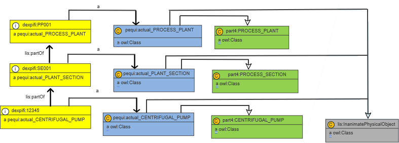
Pattern for Serial Number¶
The property SerialNumber is modelled using the assigned concept. This property can be used for different objects, like other properties. The modelling pattern is very similar to the pattern of the Identifier of the specified_PlantSection (Figure 26, Figure 27), only the cardinality (0..1) in the Restriction is different.
The definition is as follows:
prop:SerialNumber rdf:type owl:Class ;
    rdfs:label "Serial Number" ;
    rdfs:comment "A unique identification number for a product as prescribed by the manufacturer."@en ;
    skos:exactMatch part4:SERIAL_NUMBER ;
    rdfs:subClassOf lis:InformationObject .
The corresponding assignment class includes that SerialNumber is a permissible property of class actual_CentrifugalPump:
ass:SerialNumberAssignmentActivity rdf:type owl:Class ;
    rdfs:label "Serial Number Assignment Activity" ;
    rdfs:comment "Assignment for the property Serial Number."@en ;
    rdfs:subClassOf lis:Activity ;
    rdfs:subClassOf [
        a owl:Restriction ;
        owl:onProperty lis:hasPassiveParticipant ;
        owl:maxQualifiedCardinality "1"^^xsd:nonNegativeInteger ;
        owl:onClass pequi:actual_CentrifugalPump ] .
At the instance level the value of the SerialNumber is assigned to the instance dexpiass.12345 of the class actual_CentrifugalPump:
dexpifi:dexpiass.12345_SerialNumber rdf:type prop:SerialNumber ;
    lis-odp-ext:objectDatumValue "47110"^^xsd:string .

dexpifi:dexpiass.12345_SerialNumberAssignmentActivity rdf:type ass:SerialNumberAssignmentActivity ;
    lis:hasPassiveParticipant dexpifi:dexpiass.12345 ;
    lis:hasPassiveParticipant dexpifi:dexpiass.12345_SerialNumber .
Pattern for UpperLimitDesignPressure¶
In principle, there is no difference between the modelling approaches for the property UpperLimitDesignPressure of a specified_CentrifugalPump and that of an actual_CentrifugalPump. Only the bearer and the value differ.
IDO mapping for the relations between the different information structures¶
The semantic modelling of the pump life-cycle story requires two main bridges between the three primary information structures, as well as an internal bridge within the specified process plant structure between functional and physical objects. The latter one is described in Information structure for the design of a process plant. In most cases, subclassification is used. In some cases, an additional object property lis-odp-ext:specifiedTechnicalBy is applied. For the two main bridges, IDO provides suitable object properties, shown in Figure 30.

This modelling approach is similar to the intended approach of IDO, which includes the typical chain: Object → hasFunction → Function → realizedIn → Activity → hasParticipant → Object.
Process to specified Process Plant¶
Figure 31 shows the modelling solution used to relate process objects to plant objects. The object property lis:hasParticipant and its inverse lis:participantsIn relate the objects at the instance level.
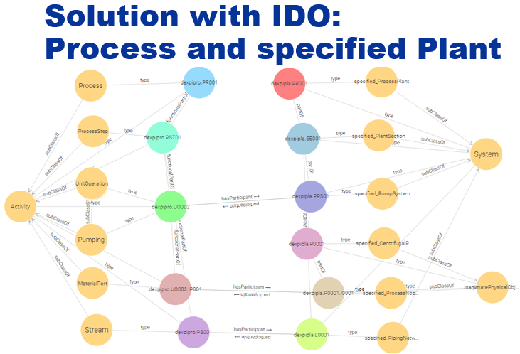
Specified Process Plant to actual Process Plant¶
The relationship between specified and actual plant objects is particularly important for maintenance systems. The object property lis:implements and its inverse lis:implementedBy relate the objects at the instance level, as shown in Figure 32.
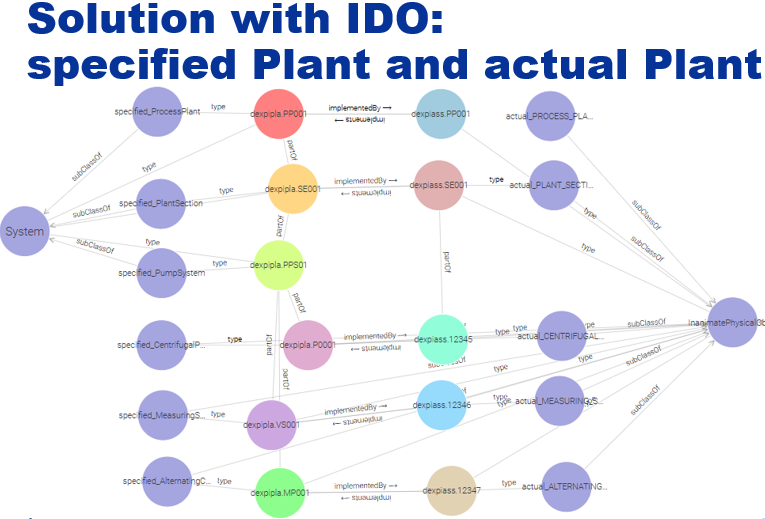
Modelling pattern for the CFIHOS interface¶
Modelling pattern for the STEP interface¶
Conclusion¶
The objectives of the fPVN Work Package 3.3 have been successfully achieved. As introduced in Introduction, the goal was to investigate how major standardized information models can be semantically interconnected using the Industrial Data Ontology (IDO). In particular, the work addressed the integration of the information models Data Exchange in the Process Industry (DEXPI), Capital Facilities Information Handover Specification (CFIHOS), and ISO 10303 application protocols 239 and 242.
To demonstrate this concept, a prototype implementation was developed based on the pump life-cycle story. The example covered the three principal information structures of the process industry lifecycle: the process structure, the specified process plant, and the actual process plant. These structures represent the typical chain from functional process design through engineering specification to the realized assets in operation.
The modelling work showed that most of the required concepts can be represented using the class hierarchy and object properties provided by IDO. In particular, IDO provides suitable mechanisms to represent the relations between lifecycle stages and to express the bridge between process design, plant specification, and realized equipment.
However, several modelling gaps were identified. The internal topology of the process structure, especially the explicit representation of dependencies between streams, ports, and unit operations, could not be fully represented using the existing IDO vocabulary. In addition, the internal bridge between specified functional objects and specified physical objects required additional modelling constructs. These gaps were addressed in the prototype by introducing supplementary concepts in an additional ontology layer below IDO. Such concepts could potentially be incorporated into future IDO releases.
Another observation concerns the typical IDO modelling chain Object → hasFunction → Function → realizedIn → Activity → hasParticipant → Object (see Handbook > The three-world model). While this pattern provides an important conceptual foundation, it does not completely match the modelling requirements of the presented lifecycle scenario. Therefore, a slightly adapted modelling approach was used for the prototype implementation.
The IDO PLM modules for Process and Equipment were not used in this work because they are currently incomplete and not actively maintained. Instead, ISO 15926 Part 4 was used as the primary reference data library. During the modelling process it became apparent that the class structure of Part 4 must be extended to clearly distinguish between specified and actual physical objects, since the base concept of InanimatePhysicalObject does not make this distinction.
Different property pattern examples have been compiled for dependent and assigned properties. However, additional domain ontologies are required, for example to cover property aspects and data types.
For the representation of units of measure, the QUDT ontology was applied instead of the IDO PLM UoM ontology. QUDT provides a comprehensive basis but required minor extensions for the present use case. For example, the physical dimension pressure had to be refined by introducing subclasses representing absolute pressure and gauge pressure.
The results of this work primarily focus on integration of DEXPI with IDO. Nevertheless, the same modelling principles can be also applied to other information models such as CFIHOS and STEP (including ISO 10303 AP239 and AP242), since the underlying life cycle information requirements are comparable.
To extend the results of Work Package 3.3 toward a more complete solution, the modelling patterns presented in Modelling pattern with IDO general solutions together with the Turtle files provided in the Appendix could be used as the basis for a semantic export of DEXPI 2.0 data into an IDO-based knowledge graph. This would require completing the different class ontologies so that they cover the full set of DEXPI 2.0 classes and properties. Based on such ontologies, DEXPI export files could be transformed automatically into instance ontologies.
Comparable semantic mappings could also be developed for CFIHOS and STEP. Establishing such mappings would provide significant benefits for industrial data interoperability. Information produced by DEXPI-, CFIHOS-, and STEP-based systems could be compared, integrated, and reused across different applications and lifecycle phases. Furthermore, the availability of semantically structured lifecycle information would enable advanced reasoning capabilities and provide an important knowledge foundation for future data-driven and AI-supported engineering solutions.
Appendix¶
Handmade XML file as input¶
<?xml version="1.0" encoding="UTF-8"?>
<!-- hand made simplified xml file for the DEXPI pump life cycle story-->
<XMLFile id="01"
xmlns="http://example.com/dexpi/core/"
xmlns:specified="http://example.com/dexpi/2.0/"
xmlns:actual="http://example.com/notindexpi/asset/"
xmlns:dexpiaddon="http://example.com/dexpi/addon/">
<specified:Process id="dexpipro.PR001">
    <Identifier>PR001</Identifier>
    <specified:ProcessStep id="dexpipro.PST01">
        <Identifier>PST01</Identifier>
        <specified:UnitOperation id="dexpipro.UO001">
            <Identifier>UO001</Identifier>
            <specified:StoringMaterial/>
            <specified:Port id="dexpipro.UO001.OP001">
                <Identifier>OP001</Identifier>
                <specified:MaterialPort/>
                <specified:PortTarget ref="dexpipro.PS001"/>
            </specified:Port>
        </specified:UnitOperation>
        <specified:UnitOperation id="dexpipro.UO002">
            <Identifier>UO002</Identifier>
            <specified:Pumping>
                <DifferentialPressure>
                    <PhysicalQuantityType>Pressure</PhysicalQuantityType>
                    <ApplicationType>PressureAbsolute</ApplicationType>
                    <UoM>Bar</UoM>
                    <Value>10</Value>
                </DifferentialPressure>
            </specified:Pumping>
            <specified:Port id="dexpipro.UO002.IP001">
                <Identifier>IP001</Identifier>
                <specified:MaterialPort/>
            </specified:Port>
            <specified:Port id="dexpipro.UO002.OP001">
                <Identifier>OP001</Identifier>
                <specified:MaterialPort/>
                <specified:PortTarget ref="dexpipro.PS002"/>
            </specified:Port>
        </specified:UnitOperation>
        <specified:UnitOperation id="dexpipro.UO003">
            <Identifier>UO003</Identifier>
            <specified:ReactingChemicals/>
            <specified:Port id="dexpipro.UO003.IP001">
                <Identifier>IP001</Identifier>
                <specified:MaterialPort/>
            </specified:Port>
        </specified:UnitOperation>
        <specified:ProcessConnection id="dexpipro.PS001">
            <Identifier>PS001</Identifier>
            <specified:Stream>
                <ConnectTo>
                    <specified:PortRef ref="dexpipro.UO002.IP001"/>
                </ConnectTo>
            </specified:Stream>
        </specified:ProcessConnection>
        <specified:ProcessConnection id="dexpipro.PS002">
            <Identifier>PS002</Identifier>
            <specified:Stream>
                <ConnectTo>
                    <specified:PortRef ref="dexpipro.UO003.IP001"/>
                </ConnectTo>
            </specified:Stream>
        </specified:ProcessConnection>
    </specified:ProcessStep>
</specified:Process>
<specified:specified_ProcessPlant id="dexpipla.PP001">
    <Identifier>PP001</Identifier>
    <Description>
        <Language>en</Language>
        <Value>I am the specified process plant of the pump life cycle story</Value>
    </Description>
    <specified:specified_PlantSection id="dexpipla.SE001">
        <Identifier>SE001</Identifier>
        <specified:specified_Pump id="dexpipla.P0001">
            <TagName>P0001</TagName>
            <DifferentialPressure>
                <PhysicalQuantityType>Pressure</PhysicalQuantityType>
                <ApplicationType>PressureAbsolute</ApplicationType>
                <UoM>Bar</UoM>
                <Value>13.5</Value>
            </DifferentialPressure>
            <specified:specified_Nozzle id="dexpipla.P0001.I0001">
                <SubTagName>I0001</SubTagName>
                <specified:specified_ProcessNozzle/>
            </specified:specified_Nozzle>
            <specified:specified_Nozzle id="dexpipla.P0001.O0001">
                <SubTagName>O0001</SubTagName>
                <specified:specified_ProcessNozzle/>
            </specified:specified_Nozzle>
            <specified:specified_Mount id="dexpipla.P0001.IM001">
                <SubTagName>IM001</SubTagName>
            </specified:specified_Mount>
            <specified:specified_CentrifugalPump>
                <LowerLimitDesignPressure>
                    <PhysicalQuantityType>Pressure</PhysicalQuantityType>
                    <ApplicationType>PressureGauge</ApplicationType>
                    <UoM>Bar</UoM>
                    <Value>-0.2</Value>
                </LowerLimitDesignPressure>
                <UpperLimitDesignPressure>
                    <PhysicalQuantityType>Pressure</PhysicalQuantityType>
                    <ApplicationType>PressureGauge</ApplicationType>
                    <UoM>Bar</UoM>
                    <Value>30</Value>
                </UpperLimitDesignPressure>
            </specified:specified_CentrifugalPump>
        </specified:specified_Pump>
        <specified:specified_Vessel id="dexpipla.V0001">
            <TagName>V0001</TagName>
            <specified:specified_Nozzle id="dexpipla.V0001.N0001">
                <SubTagName>N0001</SubTagName>
                <specified:specified_ProcessNozzle/>
            </specified:specified_Nozzle>
            <specified:specified_Tank/>
        </specified:specified_Vessel>
        <specified:specified_Vessel id="dexpipla.V0002">
            <TagName>V0002</TagName>
            <specified:specified_Nozzle id="dexpipla.V0002.N0001">
                <SubTagName>N0001</SubTagName>
                <specified:specified_ProcessNozzle/>
            </specified:specified_Nozzle>
            <specified:specified_PressureVessel/>
        </specified:specified_Vessel>
        <specified:specified_Motor id="dexpipla.MP001">
            <TagName>MP001</TagName>
            <specified:specified_AlternatingCurrentMotor/>
        </specified:specified_Motor>
        <specified:specified_PipingNetworkSystem id="dexpipla.L0001">
            <LineNumber>L0001</LineNumber>
            <specified:specified_ConnectFrom>
                <specified:specified_NozzleRef ref="dexpipla.V0001.N0001"/>
            </specified:specified_ConnectFrom>
            <specified:specified_ConnectTo>
                <specified:specified_NozzleRef ref="dexpipla.P0001.I0001"/>
            </specified:specified_ConnectTo>
        </specified:specified_PipingNetworkSystem>
        <specified:specified_PipingNetworkSystem id="dexpipla.L0002">
            <LineNumber>L0002</LineNumber>
            <specified:specified_ConnectFrom>
                <specified:specified_NozzleRef ref="dexpipla.P0001.O0001"/>
            </specified:specified_ConnectFrom>
            <specified:specified_ConnectTo>
                <specified:specified_NozzleRef ref="dexpipla.V0002.N0001"/>
            </specified:specified_ConnectTo>
        </specified:specified_PipingNetworkSystem>
        <specified:specified_ProcessInstrumentationFunction id="dexpipla.VF001">
            <ProcessInstrumentationFunctionNumber>VF001</ProcessInstrumentationFunctionNumber>
            <specified:specified_ProcessSignalGeneratingFunction id="dexpipla.VFM01">
                <ProcessSignalGeneratingFunctionNumber>VFM01</ProcessSignalGeneratingFunctionNumber>
                <SensingLocation>
                    <specified:specified_MountRef ref="dexpipla.P0001.IM001"/>
                </SensingLocation>
                <specified:specified_MeasuringSystem id="dexpipla.VS001">
                    <MeasuringSystemNumber>VS001</MeasuringSystemNumber>
                </specified:specified_MeasuringSystem>
            </specified:specified_ProcessSignalGeneratingFunction>
        </specified:specified_ProcessInstrumentationFunction>
        <specified:specified_PlantSystem id="dexpipla.PPS01">
            <PlantSystemIdentificationcode>PPS01</PlantSystemIdentificationcode>
            <specified:specified_PumpRef ref="dexpipla.P0001"/>
            <specified:specified_MotorRef ref="dexpipla.MP001"/>
            <specified:specified_ProcessInstrumentationFunctionRef ref="dexpipla.VF001"/>
        </specified:specified_PlantSystem>
    </specified:specified_PlantSection>
</specified:specified_ProcessPlant>
<actual:actual_Asset>
<actual:actual_ProcessPlant id="dexpiass.PP001">
    <Identifier>PP001</Identifier>
    <actual:actual_PlantSection id="dexpiass.SE001">
        <Identifier>SE001</Identifier>
        <actual:actual_CentrifugalPump id="dexpiass.12345">
            <EquipmentNumber>12345</EquipmentNumber>
            <VendorNumber>ABCDE</VendorNumber>
            <SerialNumber>47110</SerialNumber>
            <LowerLimitDesignPressure>
                <PhysicalQuantityType>Pressure</PhysicalQuantityType>
                <ApplicationType>PressureGauge</ApplicationType>
                <UoM>Bar</UoM>
                <Value>-0.5</Value>
            </LowerLimitDesignPressure>
            <UpperLimitDesignPressure>
                <PhysicalQuantityType>Pressure</PhysicalQuantityType>
                <ApplicationType>PressureGauge</ApplicationType>
                <UoM>Bar</UoM>
                <Value>35</Value>
            </UpperLimitDesignPressure>
        </actual:actual_CentrifugalPump>
        <actual:actual_MeasuringSystem id="dexpiass.12346">
            <EquipmentNumber>12346</EquipmentNumber>
            <VendorNumber>ABCDF</VendorNumber>
            <SerialNumber>47111</SerialNumber>
        </actual:actual_MeasuringSystem>
        <actual:actual_AlternatingCurrentMotor id="dexpiass.12347">
            <EquipmentNumber>12347</EquipmentNumber>
            <VendorNumber>ABCDG</VendorNumber>
            <SerialNumber>47112</SerialNumber>
        </actual:actual_AlternatingCurrentMotor>
    </actual:actual_PlantSection>
</actual:actual_ProcessPlant>
</actual:actual_Asset>
<dexpiaddon:Bridges>
    <dexpiaddon:Bridge id="BPP01">
        <from><specified:UnitOperationRef ref="dexpipro.UO002"/></from>
        <to><specified:specified_PlantSystemRef ref="dexpipla.PPS01"/></to>
    </dexpiaddon:Bridge>
    <dexpiaddon:Bridge id="BPP02">
        <from><specified:UnitOperationRef ref="dexpipro.UO001"/></from>
        <to><specified:specified_ProcessEquipmentRef ref="dexpipla.V0001"/></to>
    </dexpiaddon:Bridge>
    <dexpiaddon:Bridge id="BPP03">
        <from><specified:UnitOperationRef ref="dexpipro.UO003"/></from>
        <to><specified:specified_ProcessEquipmentRef ref="dexpipla.V0002"/></to>
    </dexpiaddon:Bridge>
    <dexpiaddon:Bridge id="BPP04">
        <from><specified:PortRef ref="dexpipro.UO001.OP001"/></from>
        <to><specified:specified_NozzleRef ref="dexpipla.V0001.N0001"/></to>
    </dexpiaddon:Bridge>
    <dexpiaddon:Bridge id="BPP05">
        <from><specified:PortRef ref="dexpipro.UO002.IP001"/></from>
        <to><specified:specified_NozzleRef ref="dexpipla.P0001.I0001"/></to>
    </dexpiaddon:Bridge>
    <dexpiaddon:Bridge id="BPP06">
        <from><specified:PortRef ref="dexpipro.UO002.OP001"/></from>
        <to><specified:specified_NozzleRef ref="dexpipla.P0001.O0001"/></to>
    </dexpiaddon:Bridge>
    <dexpiaddon:Bridge id="BPP07">
        <from><specified:PortRef ref="dexpipro.UO003.IP001"/></from>
        <to><specified:specified_NozzleRef ref="dexpipla.V0002.N0001"/></to>
    </dexpiaddon:Bridge>
    <dexpiaddon:Bridge id="BPP08">
        <from><specified:StreamRef ref="dexpipro.PS001"/></from>
        <to><specified:specified_PipingNetworkSystemRef ref="dexpipla.L0001"/></to>
    </dexpiaddon:Bridge>
    <dexpiaddon:Bridge id="BPP09">
        <from><specified:StreamRef ref="dexpipro.PS002"/></from>
        <to><specified:specified_PipingNetworkSystemRef ref="dexpipla.L0002"/></to>
    </dexpiaddon:Bridge>
    <dexpiaddon:Bridge id="BPA01">
        <from><specified:specified_CentrifugalPumpRef ref="dexpipla.P0001"/></from>
        <to><actual:actual_CentrifugalPumpRef ref="dexpiass.12345"/></to>
    </dexpiaddon:Bridge>
    <dexpiaddon:Bridge id="BPA02">
        <from><specified:specified_MeasuringSystemRef ref="dexpipla.VS001"/></from>
        <to><actual:actual_MeasuringSystemRef ref="dexpiass.12346"/></to>
    </dexpiaddon:Bridge>
    <dexpiaddon:Bridge id="BPA03">
        <from><specified:specified_AlternatingCurrentMotorRef ref="dexpipla.MP001"/></from>
        <to><actual:actual_AlternatingCurrentMotorRef ref="dexpiass.12347"/></to>
    </dexpiaddon:Bridge>
</dexpiaddon:Bridges>
</XMLFile>
Turtle files for the use case¶
Turtle file with the IDO extension for object properties¶
@prefix rdf: <http://www.w3.org/1999/02/22-rdf-syntax-ns#> .
@prefix rdfs: <http://www.w3.org/2000/01/rdf-schema#> .
@prefix owl: <http://www.w3.org/2002/07/owl#> .
@prefix lis: <http://rds.posccaesar.org/ontology/lis14/rdl/> .
@prefix lis-odp-ext: <http://posccaesar.org/ontology/IDO/extension-odp/> .
@prefix xsd: <http://www.w3.org/2001/XMLSchema#> .
@prefix skos: <http://www.w3.org/2004/02/skos/core#> .
@prefix dcterms: <http://purl.org/dc/terms/> .
@prefix dc: <http://purl.org/dc/elements/1.1/> .

<http://posccaesar.org/ontology/IDO/extension-odp/> a owl:Ontology ;
    rdfs:label "lis-odp-ext"@en ;
    rdfs:comment """
lis-odp-ext is an extension to the Industrial Data Ontology (IDO) that introduces
foundational terms for representing flow-oriented structures in early-stage
industrial process models. It provides classes for ports, process streams, and
unit operations, together with their associated functions and activities, and
defines flow-dependency relations between activities such as 'deliversTo' and
'feeds'.
The ontology is intended to support the semantic representation of process
block diagrams and process flow diagrams, without prescribing detailed
engineering design. It may serve as a basis for later refinement into more
detailed models, including P&IDs and equipment-level specifications.
This ontology provides additional object properties to relate functional and technical specified objects of a specified process plant. A datatype property serves for assigned properties.
"""@en ;
    owl:imports <http://rds.posccaesar.org/ontology/lis14/ont/core> ;
    dcterms:creator "Dirk Walther" ;
    dc:date "2025-03-05"^^xsd:date ;
    owl:versionInfo "0.2" .

# PortActivity
lis-odp-ext:PortActivity a owl:Class ;
    rdfs:label "Port Activity"@en ;
    rdfs:comment "A PortActivity represents the functional behaviour of a port acting either as a flow source (providing) or a flow sink (receiving), and forms the interface between a flow and a processing or streaming activity."@en ;
    rdfs:subClassOf lis:Activity .
# StreamingActivity
lis-odp-ext:StreamingActivity a owl:Class ;
    rdfs:label "Streaming Activity"@en ;
    rdfs:comment "A StreamingActivity represents the continuous flow behaviour of a process stream, transferring flow content to a downstream port or receiving flow content from an upstream port."@en ;
    rdfs:subClassOf lis:Activity .
# ProcessingActivity
lis-odp-ext:ProcessingActivity a owl:Class ;
    rdfs:label "Processing Activity"@en ;
    rdfs:comment "A ProcessingActivity represents the internal functional behaviour of a unit operation, transforming incoming flow content before delivering it to an associated output port."@en ;
    rdfs:subClassOf lis:Activity .
# SpecifiedTechnicalObject
lis-odp-ext:SpecifiedTechnicalObject a owl:Class ;
    rdfs:label "Specified Technical Object"@en ;
    rdfs:comment "A specified technical object represents the techical specification of an object."@en ;
    rdfs:subClassOf lis:InanimatePhysicalObject .
# feeds
lis-odp-ext:feeds a owl:ObjectProperty ;
    rdfs:label "feeds"@en ;
    rdfs:comment "A relation between two activities expressing that the source activity, supplies its flow content to a downstream activity that processes or re-streams it."@en ;
    rdfs:domain lis-odp-ext:PortActivity ;
    rdfs:range [
        owl:unionOf ( lis-odp-ext:ProcessingActivity lis-odp-ext:StreamingActivity )
    ] .
# fedBy
lis-odp-ext:fedBy a owl:ObjectProperty ;
    rdfs:label "is fed by"@en ;
    rdfs:comment "The inverse of 'feeds'. Indicates that an activity which processes or re-streams flow content obtains that content from an activity."@en ;
    owl:inverseOf lis-odp-ext:feeds .
# deliversTo
lis-odp-ext:deliversTo a owl:ObjectProperty ;
    rdfs:label "delivers to"@en ;
    rdfs:comment "A relation between two activities expressing that the source activity transfers its output flow content to the target activity."@en ;
    rdfs:domain [
        owl:unionOf ( lis-odp-ext:StreamingActivity lis-odp-ext:ProcessingActivity )
    ] ;
    rdfs:range lis-odp-ext:PortActivity .
# deliveredBy
lis-odp-ext:deliveredBy a owl:ObjectProperty ;
    rdfs:label "is delivered by"@en ;
    rdfs:comment "The inverse of 'delivers to'. Indicates that an activity receives its flow content from another activity that produces, transports, or otherwise generates that content."@en ;
    owl:inverseOf lis-odp-ext:deliversTo .
# to discuss, proposal for relations between specified functional and specified technical plant objects;
 # specifiesTechnical
lis-odp-ext:specifiesTechnical a owl:ObjectProperty ;
    rdfs:label "specifies technical"@en ;
    rdfs:comment "A relation between specified technical plant objects and specified functional plant objects."@en ;
    rdfs:domain lis-odp-ext:SpecifiedTechnicalObject ;
    rdfs:range lis:FunctionalObject .
# specifiedTechnicalBy
lis-odp-ext:specifiedTechnicalBy a owl:ObjectProperty ;
    rdfs:label "specified technical by"@en ;
    rdfs:comment "The inverse of 'specifies technical'. Indicates a relation between specified functional plant objects and specified technical plant objects."@en ;
    owl:inverseOf lis-odp-ext:specifiesTechnical .
# objectDatumValue
lis-odp-ext:objectDatumValue a owl:DatatypeProperty ;
    rdfs:label "objectDatumValue"@en ;
    rdfs:comment "If x has'objectDatumValue' y, then x is an information object and y a literal value."@en ;
    rdfs:domain lis:InformationObject .
Turtle file with the IDO extension for data types¶
Turtle file with the IDO extension for property aspects¶
Turtle file with properties of the use case¶
@prefix rdf: <http://www.w3.org/1999/02/22-rdf-syntax-ns#> .
@prefix rdfs: <http://www.w3.org/2000/01/rdf-schema#> .
@prefix owl: <http://www.w3.org/2002/07/owl#> .
@prefix lis: <http://rds.posccaesar.org/ontology/lis14/rdl/> .
@prefix lis-ext: <https://example.com/posccaesar/IDO/extension/> .
@prefix xsd: <http://www.w3.org/2001/XMLSchema#> .
@prefix skos: <http://www.w3.org/2004/02/skos/core#> .
@prefix dcterms: <http://purl.org/dc/terms/> .
@prefix dc: <http://purl.org/dc/elements/1.1/> .
@prefix qudt: <http://qudt.org/schema/qudt/> .
@prefix quantitykind: <http://qudt.org/vocab/quantitykind/> .
@prefix unit: <http://qudt.org/vocab/unit/> .
@prefix part4: <https://posccaesar.org/15926-4/v4/reference-data-item/> .
@prefix prop: <https://example.com/posccaesar/fPVN/properties/> .

<https://example.com/posccaesar/fPVN/properties/>
    rdf:type owl:Ontology ;
    rdfs:label "Properties fPVN project" ;
    owl:versionInfo "1.0" ;
    dc:date "2025-03-21"^^xsd:date ;
    dcterms:creator "Heiner Temmen, DEXPI e.V." ;
    rdfs:comment "Ontology for Properties of the fPVN project for DEXPI Pump life cycle story" ;
    owl:imports <file:///D:/Temmen/Heiner%20Job/GraphDB/Turtle_PLCS_lis-ext_01.ttl> .

# classes

prop:Range rdf:type owl:Class ;
    rdfs:label "Range"@en ;
    rdfs:comment "Range is an aspect of a property and indicates its range of variation."@en ;
    rdfs:subClassOf lis:Quality .

prop:UpperLimit rdf:type owl:Class ;
    rdfs:label "Upper Limit"@en ;
    rdfs:comment "A defined highest limit for the value of a property."@en ;
    rdfs:subClassOf prop:Range .

prop:Differential rdf:type owl:Class ;
    rdfs:label "Differential"@en ;
    rdfs:comment "The value indicates a difference between two values."@en ;
    rdfs:subClassOf prop:Range .

prop:Origin rdf:type owl:Class ;
    rdfs:label "Origin"@en ;
    rdfs:comment "Origin is an aspect of a property and indicates its source."@en ;
    rdfs:subClassOf lis:Quality .

prop:Specified rdf:type owl:Class ;
    rdfs:label "Specified"@en ;
    rdfs:comment "The value has been specified."@en ;
    rdfs:subClassOf prop:Origin .

prop:Calculated rdf:type owl:Class ;
    rdfs:label "Calculated"@en ;
    rdfs:comment "The value has been calculated by a formula or simulation."@en ;
    rdfs:subClassOf prop:Origin .

prop:Scope rdf:type owl:Class ;
    rdfs:label "Scope"@en ;
    rdfs:comment "Scope is an aspect of a property and indicates its area of validity."@en ;
    rdfs:subClassOf lis:Quality .

prop:Design rdf:type owl:Class ;
    rdfs:label "Design"@en ;
    rdfs:comment "The value is used for design."@en ;
    rdfs:subClassOf prop:Scope .

prop:GaugePressure rdf:type owl:Class ;
    rdfs:label "Gauge Pressure"@en ;
    rdfs:comment "A GAUGE PRESSURE is a PRESSURE that is relative to the local atmosperic pressure."@en ;
    skos:exactMatch part4:GAUGE_PRESSURE ;
    rdfs:subClassOf lis:Quality .

prop:AbsolutePressure rdf:type owl:Class ;
    rdfs:label "Absolute Pressure"@en ;
    rdfs:comment "An ABSOLUTE PRESSURE is a PRESSURE that is relative to a full vacuum."@en ;
    skos:exactMatch part4:ABSOLUTE_PRESSURE ;
    rdfs:subClassOf lis:Quality .

# prop:UpperLimitDesignPressure rdf:type owl:Class ;
#    rdfs:label "Upper Limit Design Pressure"@en ;
#    rdfs:comment "An <UPPER LIMIT DESIGN PRESSURE> is a <DESIGN PRESSURE> that refers to the highest <PRESSURE> at which a functional or physical object is designed."@en ;
#    skos:exactMatch part4:UPPER_LIMIT_DESIGN_PRESSURE ;
#    rdfs:subClassOf lis:QualityDatum ;
#    rdfs:subClassOf lis:RealMeasureTypeDatum ;
#    not yet imported as class
#    rdfs:subClassOf prop:UpperLimit ;
#    rdfs:subClassOf prop:Specified ;
#    rdfs:subClassOf prop:Design ;
#    rdfs:subClassOf prop:GaugePressure ;
#    rdfs:subClassOf [
#        a owl:Restriction ;
#       owl:onProperty qudt:hasQuantityKind ;
#       owl:hasValue quantitykind:Pressure ]  .

prop:DifferentialPressure rdf:type owl:Class ;
    rdfs:label "Differential Pressure"@en ;
    rdfs:comment "A DIFFERENTIAL PRESSURE is a PRESSURE that is relative to another PRESSURE"@en ;
    skos:exactMatch part4:DIFFERENTIAL_PRESSURE ;
    rdfs:subClassOf lis:PhysicalQuantity ;
#    rdfs:subClassOf lis:RealMeasureTypeDatum ;
#    not yet imported as class
    rdfs:subClassOf prop:Differential ;
    rdfs:subClassOf prop:Calculated ;
    rdfs:subClassOf prop:AbsolutePressure ;
    rdfs:subClassOf [
        a owl:Restriction ;
        owl:onProperty qudt:hasQuantityKind ;
        owl:hasValue quantitykind:Pressure ]  .

prop:Description rdf:type owl:Class ;
    rdfs:label "Description"@en ;
    rdfs:comment "Description of an object."@en ;
    skos:exactMatch part4:DESCRIPTION ;
    rdfs:subClassOf lis:QualityDatum .
Turtle file with process classes for the use case¶
@prefix rdf: <http://www.w3.org/1999/02/22-rdf-syntax-ns#> .
@prefix rdfs: <http://www.w3.org/2000/01/rdf-schema#> .
@prefix owl: <http://www.w3.org/2002/07/owl#> .
@prefix lis: <http://rds.posccaesar.org/ontology/lis14/rdl/> .
@prefix lis-odp-ext: <http://posccaesar.org/ontology/IDO/extension-odp/> .
@prefix xsd: <http://www.w3.org/2001/XMLSchema#> .
@prefix skos: <http://www.w3.org/2004/02/skos/core#> .
@prefix dcterms: <http://purl.org/dc/terms/> .
@prefix dc: <http://purl.org/dc/elements/1.1/> .
@prefix qudt: <http://qudt.org/schema/qudt/> .
@prefix quantitykind: <http://qudt.org/vocab/quantitykind/> .
@prefix unit: <http://qudt.org/vocab/unit/> .
@prefix part4: <https://posccaesar.org/15926-4/v4/reference-data-item/> .
@prefix prop: <http://posccaesar.org/ontology/fPVN/properties/> .
@prefix proc: <http://posccaesar.org/ontology/fPVN/process/> .

<http://posccaesar.org/ontology/fPVN/process/>
    rdf:type owl:Ontology ;
    rdfs:label "process classes fPVN project" ;
    owl:versionInfo "1.0" ;
    dc:date "2026-05-05"^^xsd:date ;
    dcterms:creator "Heiner Temmen, DEXPI e.V." ;
    rdfs:comment "Ontology for process classes of the fPVN project for DEXPI Pump life cycle story" ;
    owl:imports <file:///D:/Temmen/Heiner%20Job/GraphDB/Turtle_PLCS_lis-odp-ext_01.ttl> ;
    owl:imports <file:///D:/Temmen/Heiner%20Job/GraphDB/Turtle_PLCS_prop_01.ttl> .

# Process classes

proc:Process rdf:type owl:Class ;
        rdfs:subClassOf lis:Activity ;
    skos:exactMatch part4:PROCESS .
proc:ProcessStep rdf:type owl:Class ;
    skos:exactMatch part4:PROCESS_STEP ;
    rdfs:subClassOf lis:Activity .
proc:UnitOperation rdf:type owl:Class ;
    rdfs:subClassOf lis:Activity ;
    skos:exactMatch part4:UNIT_OPERATION .
proc:Pumping rdf:type owl:Class ;
    rdfs:subClassOf proc:UnitOperation ;
    rdfs:subClassOf lis-odp-ext:ProcessingActivity ;
    skos:exactMatch part4:PUMPING ;
    rdfs:subClassOf lis:Activity .
proc:ReactingChemicals rdf:type owl:Class ;
    rdfs:subClassOf proc:UnitOperation ;
    rdfs:subClassOf lis-odp-ext:ProcessingActivity ;
    skos:exactMatch part4:CHEMICAL_REACTING ;
    rdfs:subClassOf lis:Activity .
proc:StoringMaterial rdf:type owl:Class ;
    rdfs:subClassOf proc:UnitOperation ;
    rdfs:subClassOf lis-odp-ext:ProcessingActivity ;
    skos:exactMatch part4:STORING ;
    rdfs:subClassOf lis:Activity .
proc:Port rdf:type owl:Class ;
    skos:exactMatch part4:PORT ;
    rdfs:subClassOf lis:Activity .
proc:MaterialPort rdf:type owl:Class ;
    rdfs:subClassOf proc:Port ;
    rdfs:subClassOf lis-odp-ext:PortActivity ;
    rdfs:subClassOf lis:Activity ;
    skos:exactMatch part4:PORT_in_transport .
proc:ProcessConnection rdf:type owl:Class ;
    skos:exactMatch part4:Stream ;
    rdfs:subClassOf lis:Activity .
proc:Stream rdf:type owl:Class ;
    rdfs:subClassOf proc:ProcessConnection ;
    rdfs:subClassOf lis-odp-ext:StreamingActivity ;
    skos:exactMatch part4:PROCESS_STREAM ;
    rdfs:subClassOf lis:Activity .
Turtle file with specified process plant classes for the use case¶
@prefix rdf: <http://www.w3.org/1999/02/22-rdf-syntax-ns#> .
@prefix rdfs: <http://www.w3.org/2000/01/rdf-schema#> .
@prefix owl: <http://www.w3.org/2002/07/owl#> .
@prefix lis: <http://rds.posccaesar.org/ontology/lis14/rdl/> .
@prefix lis-odp-ext: <http://posccaesar.org/ontology/IDO/extension-odp/> .
@prefix xsd: <http://www.w3.org/2001/XMLSchema#> .
@prefix skos: <http://www.w3.org/2004/02/skos/core#> .
@prefix dcterms: <http://purl.org/dc/terms/> .
@prefix dc: <http://purl.org/dc/elements/1.1/> .
@prefix qudt: <http://qudt.org/schema/qudt/> .
@prefix quantitykind: <http://qudt.org/vocab/quantitykind/> .
@prefix unit: <http://qudt.org/vocab/unit/> .
@prefix part4: <https://posccaesar.org/15926-4/v4/reference-data-item/> .
@prefix prop: <http://posccaesar.org/ontology/fPVN/properties/> .
@prefix spla: <http://posccaesar.org/ontology/fPVN/specifiedPlant/> .

<http://posccaesar.org/ontology/fPVN/specifiedPlant/>
    rdf:type owl:Ontology ;
    rdfs:label "specified plant classes fPVN project" ;
    owl:versionInfo "1.0" ;
    dc:date "2026-05-08"^^xsd:date ;
    dcterms:creator "Heiner Temmen, DEXPI e.V." ;
    rdfs:comment "Ontology for specified plant classes of the fPVN project for DEXPI Pump life cycle story" ;
    owl:imports <file:///D:/Temmen/Heiner%20Job/GraphDB/Turtle_PLCS_lis-odp-ext_01.ttl> ;
    owl:imports <file:///D:/Temmen/Heiner%20Job/GraphDB/Turtle_PLCS_prop_01.ttl> .

# classes for specified Process Plant

spla:specified_ProcessPlant rdf:type owl:Class ;
    rdfs:subClassOf lis:System ;
    rdfs:subClassOf part4:PROCESS_PLANT .
spla:specified_PlantSection rdf:type owl:Class ;
    rdfs:subClassOf lis:System ;
    rdfs:subClassOf part4:PLANT_SECTION .
#   owl:HasKey prop:identifier
spla:specified_PumpSystem rdf:type owl:Class ;
    rdfs:subClassOf lis:System ;
    rdfs:subClassOf part4:PUMP_SYSTEM .
spla:specified_Pump rdf:type owl:Class ;
    rdfs:subClassOf lis:System ;
    rdfs:subClassOf part4:PUMP ;
    rdfs:subClassOf [
            a owl:Restriction ;
            owl:onProperty lis:hasQuality ;
            owl:maxQualifiedCardinality "1"^^xsd:nonNegativeInteger ;
            owl:onClass prop:DifferentialPressure ] .
spla:specified_CentrifugalPump
    rdf:type owl:Class ;
        rdfs:subClassOf lis:InanimatePhysicalObject ;
    rdfs:subClassOf part4:CENTRIFUGAL_PUMP ;
    rdfs:subClassOf spla:specified_Pump ;
        rdfs:subClassOf [
            a owl:Restriction ;
            owl:onProperty lis:hasQuality ;
            owl:maxQualifiedCardinality "1"^^xsd:nonNegativeInteger ;
            owl:onClass prop:UpperLimitDesignPressure ] .
spla:specified_ProcessNozzle rdf:type owl:Class ;
    rdfs:subClassOf lis:InanimatePhysicalObject ;
    rdfs:subClassOf part4:PROCESS_NOZZLE .
spla:specified_Motor rdf:type owl:Class ;
    rdfs:subClassOf lis:System ;
    rdfs:subClassOf part4:ELECTRIC_MOTOR .
spla:specified_AlternatingCurrentMotor rdf:type owl:Class ;
    rdfs:subClassOf lis:InanimatePhysicalObject ;
    rdfs:subClassOf spla:specified_Motor ;
    rdfs:subClassOf part4:ALTERNATING_CURRENT_MOTOR .
spla:specified_ProcessInstrumentationFunction rdf:type owl:Class ;
    rdfs:subClassOf lis:System ;
    rdfs:subClassOf part4:INSTRUMENTATION_FUNCTION .
spla:specified_ProcessSignalGeneratingFunction rdf:type owl:Class ;
    rdfs:subClassOf lis:System ;
    rdfs:subClassOf part4:PROCESS_SIGNAL_GENERATING_FUNCTION .
spla:specified_MeasuringSystem rdf:type owl:Class ;
    rdfs:subClassOf lis:InanimatePhysicalObject ;
    rdfs:subClassOf part4:MEASURING_SYSTEM ;
    rdfs:subClassOf lis-odp-ext:SpecifiedTechnicalObject.
spla:specified_PipingNetworkSystem rdf:type owl:Class ;
    rdfs:subClassOf lis:System ;
    rdfs:subClassOf part4:PIPING_NETWORK_SYSTEM .
Turtle file with actual process plant classes for the use case¶
@prefix rdf: <http://www.w3.org/1999/02/22-rdf-syntax-ns#> .
@prefix rdfs: <http://www.w3.org/2000/01/rdf-schema#> .
@prefix owl: <http://www.w3.org/2002/07/owl#> .
@prefix lis: <http://rds.posccaesar.org/ontology/lis14/rdl/> .
@prefix lis-odp-ext: <http://posccaesar.org/ontology/IDO/extension-odp/> .
@prefix xsd: <http://www.w3.org/2001/XMLSchema#> .
@prefix skos: <http://www.w3.org/2004/02/skos/core#> .
@prefix dcterms: <http://purl.org/dc/terms/> .
@prefix dc: <http://purl.org/dc/elements/1.1/> .
@prefix qudt: <http://qudt.org/schema/qudt/> .
@prefix quantitykind: <http://qudt.org/vocab/quantitykind/> .
@prefix unit: <http://qudt.org/vocab/unit/> .
@prefix part4: <https://posccaesar.org/15926-4/v4/reference-data-item/> .
@prefix prop: <http://posccaesar.org/ontology/fPVN/properties/> .
@prefix pequi: <http://posccaesar.org/ontology/fPVN/physicalEquipment/> .

<http://posccaesar.org/ontology/fPVN/physicalEquipment/>
    rdf:type owl:Ontology ;
    rdfs:label "physical equipment classes fPVN project" ;
    owl:versionInfo "1.0" ;
    dc:date "2026-05-08"^^xsd:date ;
    dcterms:creator "Heiner Temmen, DEXPI e.V." ;
    rdfs:comment "Ontology for physical equipment classes of the fPVN project for DEXPI Pump life cycle story" ;
    owl:imports <file:///D:/Temmen/Heiner%20Job/GraphDB/Turtle_PLCS_lis-odp-ext_01.ttl> ;
    owl:imports <file:///D:/Temmen/Heiner%20Job/GraphDB/Turtle_PLCS_prop_01.ttl> .

# classes for actual Process Plant

pequi:actual_ProcessPlant rdf:type owl:Class ;
    rdfs:subClassOf lis:InanimatePhysicalObject ;
    rdfs:subClassOf part4:PROCESS_PLANT .
pequi:actual_PlantSection rdf:type owl:Class ;
    rdfs:subClassOf lis:InanimatePhysicalObject ;
    rdfs:subClassOf part4:PLANT_SECTION .
pequi:actual_CentrifugalPump
    rdf:type owl:Class ;
        rdfs:subClassOf lis:InanimatePhysicalObject ;
    rdfs:subClassOf part4:CENTRIFUGAL_PUMP ;
        rdfs:subClassOf [
            a owl:Restriction ;
            owl:onProperty lis:hasQuality ;
            owl:maxQualifiedCardinality "1"^^xsd:nonNegativeInteger ;
            owl:onClass prop:UpperLimitDesignPressure ] .
pequi:actual_AlternatingCurrentMotor rdf:type owl:Class ;
    rdfs:subClassOf lis:InanimatePhysicalObject ;
    rdfs:subClassOf part4:ALTERNATING_CURRENT_MOTOR .
pequi:actual_MeasuringSystem rdf:type owl:Class ;
    rdfs:subClassOf lis:InanimatePhysicalObject ;
    rdfs:subClassOf part4:MEASURING_SYSTEM .
Turtle file with property assignments for the use case¶
@prefix rdf: <http://www.w3.org/1999/02/22-rdf-syntax-ns#> .
@prefix rdfs: <http://www.w3.org/2000/01/rdf-schema#> .
@prefix owl: <http://www.w3.org/2002/07/owl#> .
@prefix lis: <http://rds.posccaesar.org/ontology/lis14/rdl/> .
@prefix lis-odp-ext: <http://posccaesar.org/ontology/IDO/extension-odp/> .
@prefix xsd: <http://www.w3.org/2001/XMLSchema#> .
@prefix skos: <http://www.w3.org/2004/02/skos/core#> .
@prefix dcterms: <http://purl.org/dc/terms/> .
@prefix dc: <http://purl.org/dc/elements/1.1/> .
@prefix qudt: <http://qudt.org/schema/qudt/> .
@prefix quantitykind: <http://qudt.org/vocab/quantitykind/> .
@prefix unit: <http://qudt.org/vocab/unit/> .
@prefix part4: <https://posccaesar.org/15926-4/v4/reference-data-item/> .
@prefix prop: <http://posccaesar.org/ontology/fPVN/properties/> .
@prefix proc: <http://posccaesar.org/ontology/fPVN/Process/> .
@prefix spla: <http://posccaesar.org/ontology/fPVN/specifiedPlant/> .
@prefix pequi: <http://posccaesar.org/ontology/fPVN/actualPlant/> .
@prefix ass: <http://posccaesar.org/ontology/fPVN/assignments/> .

<http://posccaesar.org/ontology/fPVN/assignments/>
    rdf:type owl:Ontology ;
    rdfs:label "Assignments fPVN project" ;
    owl:versionInfo "1.0" ;
    dc:date "2026-05-08"^^xsd:date ;
    dcterms:creator "Heiner Temmen, DEXPI e.V." ;
    rdfs:comment "Ontology for assigning properties of the fPVN project for DEXPI Pump life cycle story" ;
    owl:imports <file:///D:/Temmen/Heiner%20Job/GraphDB/Turtle_PLCS_lis-odp-ext_01.ttl> ;
    owl:imports <file:///D:/Temmen/Heiner%20Job/GraphDB/Turtle_PLCS_proc_01.ttl> .
    owl:imports <file:///D:/Temmen/Heiner%20Job/GraphDB/Turtle_PLCS_spla_01.ttl> .
    owl:imports <file:///D:/Temmen/Heiner%20Job/GraphDB/Turtle_PLCS_pequi_01.ttl> .

# classes

ass:IdentifierAssignmentActivity rdf:type owl:Class ;
    rdfs:label "Identifier Assignment Activity" ;
    rdfs:comment "Assignment for the property Identifier."@en ;
    rdfs:subClassOf lis:Activity ;
    rdfs:subClassOf [
                a owl:Restriction ;
            owl:onProperty lis:hasPassiveParticipant ;
            owl:qualifiedCardinality "1"^^xsd:nonNegativeInteger ;
                owl:onClass spla:PlantSection ];
    rdfs:subClassOf [
                a owl:Restriction ;
            owl:onProperty lis:hasPassiveParticipant ;
            owl:qualifiedCardinality "1"^^xsd:nonNegativeInteger ;
                owl:onClass pequi:CentrifugalPump ] .

ass:ObjectDescriptionAssignmentActivity rdf:type owl:Class ;
    rdfs:label "ObjectDescription Assignment Activity" ;
    rdfs:comment "Assignment for the property ObjectDescription."@en ;
    rdfs:subClassOf lis:Activity ;
    rdfs:subClassOf [
                a owl:Restriction ;
            owl:onProperty lis:hasPassiveParticipant ;
            owl:maxQualifiedCardinality "1"^^xsd:nonNegativeInteger ;
                owl:onClass spla:specified_ProcessPlant ] .

ass:SerialNumberAssignmentActivity rdf:type owl:Class ;
    rdfs:label "Serial Number Assignment Activity" ;
    rdfs:comment "Assignment for the property Serial Number."@en ;
    rdfs:subClassOf lis:Activity ;
    rdfs:subClassOf [
                a owl:Restriction ;
            owl:onProperty lis:hasPassiveParticipant ;
            owl:maxQualifiedCardinality "1"^^xsd:nonNegativeInteger ;
                owl:onClass pequi:actual_CentrifugalPump ] .
Turtle file with instances for the use case¶
@prefix rdf: <http://www.w3.org/1999/02/22-rdf-syntax-ns#> .
@prefix rdfs: <http://www.w3.org/2000/01/rdf-schema#> .
@prefix owl: <http://www.w3.org/2002/07/owl#> .
@prefix lis: <http://rds.posccaesar.org/ontology/lis14/rdl/> .
@prefix lis-odp-ext: <http://posccaesar.org/ontology/IDO/extension-odp/> .
@prefix xsd: <http://www.w3.org/2001/XMLSchema#> .
@prefix skos: <http://www.w3.org/2004/02/skos/core#> .
@prefix dcterms: <http://purl.org/dc/terms/> .
@prefix dc: <http://purl.org/dc/elements/1.1/> .
@prefix qudt: <http://qudt.org/schema/qudt/> .
@prefix quantitykind: <http://qudt.org/vocab/quantitykind/> .
@prefix unit: <http://qudt.org/vocab/unit/> .
@prefix part4: <https://posccaesar.org/15926-4/v4/reference-data-item/> .
@prefix prop: <http://posccaesar.org/ontology/fPVN/properties/> .
@prefix proc: <http://posccaesar.org/ontology/fPVN/process/> .
@prefix spla: <http://posccaesar.org/ontology/fPVN/specifiedPlant/> .
@prefix pequi: <http://posccaesar.org/ontology/fPVN/physicalEquipment/> .
@prefix ass: <http://posccaesar.org/ontology/fPVN/assignments/> .
@prefix daty: <http://posccaesar.org/ontology/quality-datum-data-type/rdl#> .

@prefix dexpifi: <file:///D:/Temmen/DEXPI_File_02.xml#> .

<http://posccaesar.org/ontology/fPVN/instances/>
    rdf:type owl:Ontology ;
    rdfs:label "instances fPVN project" ;
   owl:versionInfo "1.0" ;
   dc:date "2026-05-08"^^xsd:date ;
   dcterms:creator "Heiner Temmen, DEXPI e.V." ;
   rdfs:comment "Ontology for instances of the fPVN project for DEXPI Pump life cycle story" ;
   owl:imports <file:///D:/Temmen/Heiner%20Job/GraphDB/Turtle_PLCS_lis-odp-ext_01.ttl> ;
   owl:imports <file:///D:/Temmen/Heiner%20Job/GraphDB/Turtle_PLCS_prop_01.ttl> ;
   owl:imports <file:///D:/Temmen/Heiner%20Job/GraphDB/Turtle_PLCS_proc_01.ttl> ;
   owl:imports <file:///D:/Temmen/Heiner%20Job/GraphDB/Turtle_PLCS_spla_01.ttl> ;
   owl:imports <file:///D:/Temmen/Heiner%20Job/GraphDB/Turtle_PLCS_ass_01.ttl> ;
   owl:imports <file:///D:/Temmen/Heiner%20Job/GraphDB/Turtle_PLCS_pequi_01.ttl> .

# Process instances, some examples

dexpifi:dexpipro.PR001 rdf:type proc:Process .
dexpifi:dexpipro.PST01 rdf:type proc:ProcessStep ;
    lis:PartOf dexpifi:dexpipro.PR001 .
dexpifi:dexpipro.UO002 rdf:type proc:Pumping ;
    lis:PartOf dexpifi:dexpipro.PST01 .
dexpifi:dexpipro.UO002.IP001 rdf:type proc:MaterialPort ;
    lis:PartOf dexpifi:dexpipro.UO002 .
dexpifi:dexpipro.UO002.OP001 rdf:type proc:MaterialPort ;
    lis:PartOf dexpifi:dexpipro.UO002 .
dexpifi:dexpipro.PS001 rdf:type proc:Stream ;
    lis:PartOf dexpifi:dexpipro.PST01 .
dexpifi:dexpipro.PS002 rdf:type proc:Stream ;
    lis:PartOf dexpifi:dexpipro.PST01 .
dexpifi:dexpipro.PS001 lis-odp-ext:deliversTo dexpifi:dexpipro.UO002.IP001 .
dexpifi:dexpipro.UO002.IP001 lis-odp-ext:feeds dexpifi:dexpipro.UO002 .
dexpifi:dexpipro.UO002 lis-odp-ext:deliversTo dexpifi:dexpipro.UO002.OP001 .
dexpifi:dexpipro.UO002.OP001 lis-odp-ext:deliversTo dexpifi:dexpipro.PS002 .

# instance for specified Process Plant with property, example

dexpifi:dexpipla.PP001 rdf:type spla:specified_ProcessPlant .
dexpifi:dexpipla.PP001_ObjectDescription rdf:type prop:ObjectDescription ;
    lis-odp-ext:objectDatumValue "I am the specified process plant of the pump life cycle story"^^xsd:string .
dexpifi:dexpipla.PP001_ObjectDescriptionAssignmentActivity rdf:type ass:ObjectDescriptionAssignmentActivity ;
    lis:hasPassiveParticipant dexpifi:dexpipla.PP001 ;
    lis:hasPassiveParticipant dexpifi:dexpipla.PP001_ObjectDescription .

# instance for specified Plant Section with property, example

dexpifi:dexpipla.SE001 rdf:type spla:specified_PlantSection ;
    lis:partOf dexpifi:dexpipla.PP001 .
dexpifi:dexpipla.SE001_Identifier rdf:type prop:Identifier ;
    lis-odp-ext:objectDatumValue "SE001"^^xsd:string  .
dexpifi:dexpipla.SE001_IdentifierAssignmentActivity rdf:type ass:IdentifierAssignmentActivity ;
    lis:hasPassiveParticipant dexpifi:dexpipla.SE001 ;
    lis:hasPassiveParticipant dexpifi:dexpipla.SE001_Identifier .

dexpifi:dexpipla.PPS01 rdf:type spla:specified_PumpSystem ;
    lis:partOf dexpifi:dexpipla.SE001 .
dexpifi:dexpipla.P0001 rdf:type spla:specified_CentrifugalPump ;
    lis:partOf dexpifi:dexpipla.PPS01 .
dexpifi:dexpipla.P0001.I0001 rdf:type spla:specified_ProcessNozzle ;
    lis:partOf dexpifi:dexpipla.P0001 ;
    lis:connectedTo dexpifi:dexpipla.P0001 .
dexpifi:dexpipla.VF001 rdf:type spla:specified_ProcessInstrumentationFunction ;
    lis:partOf dexpifi:dexpipla.PPS01 .
dexpifi:dexpipla.VFM01 rdf:type spla:specified_ProcessSignalGeneratingFunction ;
    lis:partOf dexpifi:dexpipla.VF001 ;
    lis-odp-ext:specifiedTechnicalBy dexpifi:dexpipla.VS001 .
dexpifi:dexpipla.VS001 rdf:type spla:specified_MeasuringSystem ;
    lis-odp-ext:specifiesTechnical dexpifi:dexpipla.VFM01 .
dexpifi:dexpipla.MP001 rdf:type spla:specified_Motor ;
    lis:partOf dexpifi:dexpipla.PPS01 ;
    rdf:type spla:specified_AlternatingCurrentMotor .
dexpifi:dexpipla.L0001 rdf:type spla:specified_PipingNetworkSystem ;
    lis:partOf dexpifi:dexpipla.SE001 ;
    lis:connectedTo dexpifi:dexpipla.P0001.I0001 .

# instance for specified Pump with property, example
dexpifi:dexpipla.P0001 rdf:type spla:specified_Pump ;
    lis:hasQuality dexpifi:dexpipla.P0001_DifferentialPressure .
dexpifi:dexpipla.P0001_DifferentialPressure rdf:type prop:DifferentialPressure ;
    lis:qualityQuantifiedAs dexpifi:dexpipla.P0001_DifferentialPressure_value .
dexpifi:dexpipla.P0001_DifferentialPressure_value rdf:type owl:NamedIndividual ;
    lis:datumUOM unit:BAR ;
    lis:datumValue "13.5"^^xsd:double .

# instance for specified CentrifugalPump with property, example
dexpifi:dexpipla.P0001 rdf:type spla:specified_CentrifugalPump ;
    lis:hasQuality dexpifi:dexpipla.P0001_UpperLimitDesignPressure .
dexpifi:dexpipla.P0001_UpperLimitDesignPressure rdf:type prop:UpperLimitDesignPressure ;
    lis:qualityQuantifiedAs dexpifi:dexpipla.P0001_UpperLimitDesignPressure_value .
dexpifi:dexpipla.P0001_UpperLimitDesignPressure_value rdf:type owl:NamedIndividual ;
    lis:datumUOM unit:BAR ;
    lis:datumValue "30.0"^^xsd:double .

# instance for actual Process Plant, example

dexpifi:dexpiass.PP001 rdf:type pequi:actual_ProcessPlant .
dexpifi:dexpiass.SE001 rdf:type pequi:actual_PlantSection ;
    lis:partOf dexpifi:dexpiass.PP001 .

dexpifi:dexpiass.12345 rdf:type pequi:actual_CentrifugalPump ;
    lis:partOf dexpifi:dexpiass.SE001 .
# instance for actual CentrifugalPump with property, example
dexpifi:dexpiass.12345 rdf:type pequi:actual_CentrifugalPump ;
    lis:hasQuality dexpifi:dexpiass.12345_UpperLimitDesignPressure .
dexpifi:dexpiass.12345_UpperLimitDesignPressure rdf:type prop:UpperLimitDesignPressure ;
    lis:qualityQuantifiedAs dexpifi:dexpiass.12345_UpperLimitDesignPressure_value .
dexpifi:dexpiass.12345_UpperLimitDesignPressure_value rdf:type owl:NamedIndividual ;
    lis:datumUOM unit:BAR ;
    lis:datumValue "35.0"^^xsd:double .
dexpifi:dexpiass.12345_Identifier rdf:type prop:Identifier ;
    lis-odp-ext:objectDatumValue "12345"^^xsd:string  .
dexpifi:dexpiass.12345_IdentifierAssignmentActivity rdf:type ass:IdentifierAssignmentActivity ;
    lis:hasPassiveParticipant dexpifi:dexpiass.12345 ;
    lis:hasPassiveParticipant dexpifi:dexpiass.12345_Identifier .
dexpifi:dexpiass.12345_SerialNumber rdf:type prop:SerialNumber ;
    lis-odp-ext:objectDatumValue "47110"^^xsd:string  .
dexpifi:dexpiass.12345_SerialNumberAssignmentActivity rdf:type ass:SerialNumberAssignmentActivity ;
    lis:hasPassiveParticipant dexpifi:dexpiass.12345 ;
    lis:hasPassiveParticipant dexpifi:dexpiass.12345_SerialNumber .

dexpifi:dexpiass.12346 rdf:type pequi:actual_MeasuringSystem ;
    lis:partOf dexpifi:dexpiass.SE001 .
dexpifi:dexpiass.12347 rdf:type pequi:actual_AlternatingCurrentMotor ;
    lis:partOf dexpifi:dexpiass.SE001 .

# Relations between Process and specified Plant objects

dexpifi:dexpipro.UO002 lis:hasParticipant dexpifi:dexpipla.PPS01 .
dexpifi:dexpipla.PPS01 lis:participantsIn dexpifi:dexpipro.UO002 .
dexpifi:dexpipro.PS001 lis:hasParticipant dexpifi:dexpipla.L0001 .
dexpifi:dexpipla.L0001 lis:participantsIn dexpifi:dexpipro.PS001 .
dexpifi:dexpipro.UO002.IP001 lis:hasParticipant dexpifi:dexpipla.P0001.I0001 .
dexpifi:dexpipla.P0001.I0001 lis:participantsIn dexpifi:dexpipro.UO002.IP001 .

# Relations between specified Plant objects and actual Plant objects

dexpifi:dexpipla.PP001 lis:implementedBy dexpifi:dexpiass.PP001 .
dexpifi:dexpiass.PP001 lis:implements dexpifi:dexpipla.PP001 .
dexpifi:dexpipla.SE001 lis:implementedBy dexpifi:dexpiass.SE001 .
dexpifi:dexpiass.SE001 lis:implements dexpifi:dexpipla.SE001 .
dexpifi:dexpipla.P0001 lis:implementedBy dexpifi:dexpiass.12345 .
dexpifi:dexpiass.12345 lis:implements dexpifi:dexpipla.P0001 .
dexpifi:dexpipla.VS001 lis:implementedBy dexpifi:dexpiass.12346 .
dexpifi:dexpiass.12346 lis:implements dexpifi:dexpipla.VS001 .
dexpifi:dexpipla.MP001 lis:implementedBy dexpifi:dexpiass.12347 .
dexpifi:dexpiass.12347 lis:implements dexpifi:dexpipla.MP001 .
References¶
[1] O. Paap, CFIHOS Semantic Guide, … , 2026.
[2] T. Holm, Step and DEXPI to IDO, … , 2026.
[3] A. Neumann, Property decomposition concepts, … , 2026.
[4] DEXPI home page. (n.d.). Retrieved 07 16, 2024, from www.dexpi.org
| Version | Date | Description |
|---|---|---|
| 0.1 | 2026-02 | First draft for review |
| 0.2 | 2026-03-08 | Draft for review of chapters 1, 2, 3, 4, 5 (partly), 6 and 7 |
| 0.3 | 2026-04-13 | Very small changes in chapters 1–4; improvements in chapters 5, 6, 7 |
| 0.4 | 2026-05-01 | Chapters 1–4: ready; chapter 5, … still under construction |
| 0.5 | 2026-05-08 | Last chapters completed |
Systematic Decomposition of Physical Quantities, Properties, and Values Using an Example of the Process Industry¶
Introduction¶
How can complex technical contexts be structured so that they are clear and traceable for both experts and machine processing?
This document presents a general method for the decomposition of physical quantities, properties, and values—illustrated using the example of the process industry. The focus is on the question: How can implicit expert knowledge be broken down into explicit, reusable basic building blocks?
The following aspects are addressed:
-
Properties (e.g., Differential Pressure, Design Pressure) and their bearers (process activities, specifications, equipment) are analyzed.
-
Properties are considered in the context of their bearers, as their meaning and values may vary depending on the context.
-
Values (including ranges, units, formats) are systematically described.
-
Basic building blocks (physical quantities, properties, bearers, values) and their relationships are defined.
-
International standards (e.g., API 610, IEC 61360-1, ISO/IEC 80000, etc.) are included as a reference framework.
-
Existing ontologies (focus is on IDO, QUDT) are used to build on established models—and extension requirements are identified that are necessary for complete modeling.
The result is a traceable, applicable decomposition that makes expert knowledge explicit and simultaneously forms the basis for ontological modelling.
Using the example of pressure (as a physical quantity), it is shown how the method works in practice—without being limited to the process industry.
This document focuses on the decomposition of properties as technical specifications (e.g., permissible ranges for Design Pressure) like shown in Figure 33, which can later serve as the basis for measurements or designs. Concrete measured values (e.g., measured pressures) are deliberately not considered—refer to Aspects Not Covered in the Decomposition for this.
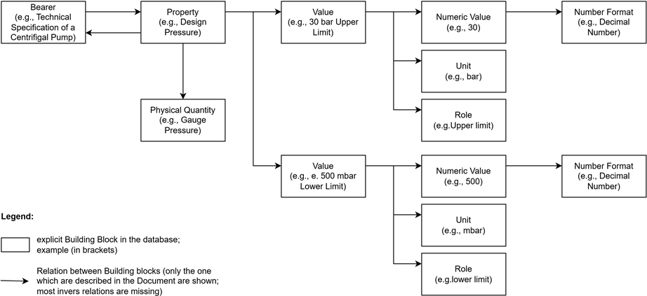
Integration with Practical Data Structures explores how the decomposition approach could be extended to link with practical data structures—such as those found in databases—where not all elements of the full model are explicitly available. Rather than prescribing a fixed solution. Figure 34 and Figure 35 show possible scenarios. They are only mentioned in this document but not fully developed.
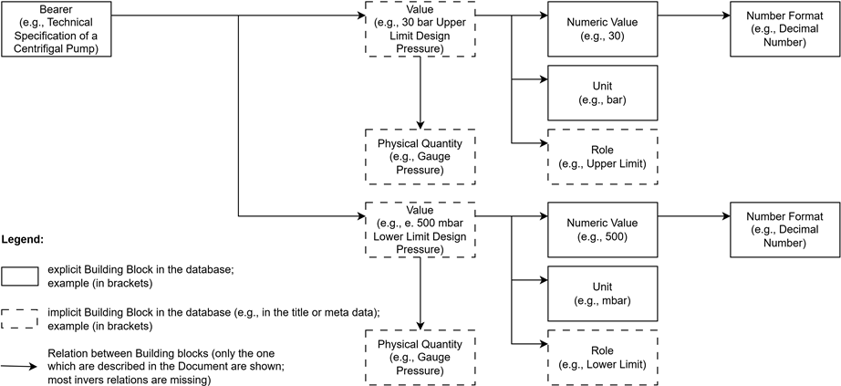
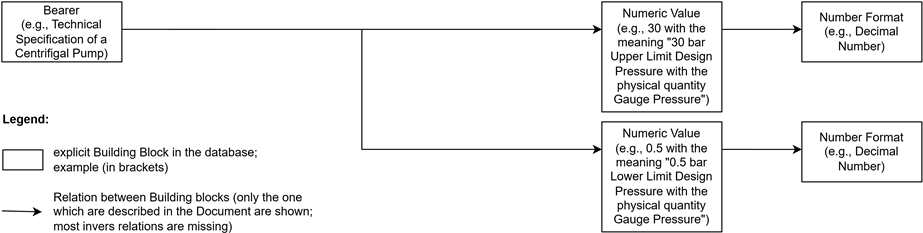
The decomposition of values and properties including their relationships to bearers developed in this document is not merely a methodological breakdown, but also forms the basis for their formal representation. To decompose expert knowledge in detail and make it usable for digital applications, it is transferred into an ontology-based model. This model relies on standards such as the Industrial Data Ontology (IDO) and the Quantities, Units, Dimensions, and Types Ontology (QUDT), which provide classes and relationships for basic building blocks such as physical quantities, units, properties, bearers, etc.
Building on this, the decomposition enables subsequent integration into databases or exchange formats—even though the detailed elaboration (see Integration with Practical Data Structures) is not part of this document. Key aspects addressed here are on the machine-processability and interoperability of the decomposed information. At the same time, gaps in the ontologies are identified, for which proposals for extensions are developed as a basis for discussion.
Properties in the Process Industry¶
In the process industry, properties such as Differential Pressure or Design Pressure are quantified by values of the physical quantity pressure. The property itself (e.g., Differential Pressure) describes a characteristic of a system, while the value (e.g., 10 bar) specifies the concrete manifestation of this characteristic.
This distinction between property and value corresponds to the ontological practice according to IEC 61360-1 and enables a clear assignment of physical quantities to technical properties and its values.
In the process industry, the bearers of the properties Differential Pressure and Design Pressure are differentiated as follows—with the bearer assignment following the phases of the lifecycle of a pump:
-
Differential Pressure is a property also described as absolute pressure or pressure difference (Δp) (details see Basic Building Blocks). It can be concretized as follows:
-
As a property of the process activity (e.g., Pumping Activity in the process). This describes a functional requirement for the process (e.g., "The process activity must ensure a pressure difference of 10 bar").
-
As a property of the general pump (plant description). This describes a functional requirement for a still unspecified pump (e.g., "The pump must ensure a pressure difference of 13.5 bar").
-
Design Pressure is a property describing a relative pressure (gauge pressure) (details see Basic Building Blocks) and undergoes the following concretizations:
-
Property of the specified centrifugal pump (technical specification): After selecting the pump type, Design Pressure is defined as a constructive property of the pump to be used (e.g., "as per, e.g., API 610 with Upper Limit Design Pressure 33.5 bar").
-
Property of the actual centrifugal pump (physical equipment): The Design Pressure is a certified property of the finished product (e.g., "Pump type xyz with Upper Limit Design Pressure 38 bar").
The higher upper limit value of the property Design Pressure assigned to the actual centrifugal pump (38 bar) takes into account additional safety margins of the certification (as per, e.g., API 610, Section 5.2.3.4). This step-by-step assignment of properties to their bearers—from process requirements to physical equipment—follows the technical and organizational specifications from standards (e.g., API 610 or ISO 14224). It enables a clear separation between process-related and equipment-related requirements and ensures that the functional and constructive properties of a system are traceably documented in every phase of the lifecycle.
Calculation of Design Pressure¶
The transition from Differential Pressure to Design Pressure is carried out through a technical calculation that, in addition to the differential pressure (Δp), also takes into account the initial pressure (p~1~) at the pump inlet as well as other parameters:
-
Input quantities: The initial pressure (p~1~) of, for example, 15 bar and the Differential Pressure (Δp) of the general pump in the plant description (e.g., 13.5 bar according to Properties in the Process Industry) are supplemented by geodetic heights, friction losses, and safety allowances (as per, e.g., API 610 or ASME B31.3) to determine the maximum operating pressure.
-
Design Pressure as a range: The result is not a single value, but a pressure range with:
-
Upper Limit (e.g., 33.5 bar, calculated from p~1~ = 15 bar + Δp = 13.5 bar + 5 bar safety allowance): Maximum pressure load capacity of the equipment.
-
Lower Limit (e.g., 0.5 bar or 500 mbar): Minimum permissible relative pressure (e.g., to avoid cavitation, as per, e.g., API 610).
The calculation of the Design Pressure follows the technical specifications of e.g., API 610 or ASME B31.3—particularly for the consideration of safety allowances and geodetic heights. This ensures that the equipment can handle both overpressure and underpressure, which is essential for the design of pumps and piping systems.
Representation of the Value of a Property¶
The representation of the value of a property—such as Design Pressure or Differential Pressure—requires a defined format to ensure the necessary precision and clarity. This is essential for the following reasons:
-
Precision for Technical Applications: The numerical value is typically specified as a decimal number (e.g., 0.5) to reflect the precision required in technical contexts. The following applies:
-
Decimal separator: Dot or comma, according to technical conventions (e.g., DIN 1333 for scientific and technical representations).
-
Significant digits: The number of decimal places (e.g., one or two) is based on the application requirements—such as the required measurement accuracy or tolerance limits.
-
-
Consistency Across Different Properties: The format is independent of the specific property (e.g., pressure or temperature) and thus enables a uniform representation. This ensures that numerical values can be understood without additional explanations—a fundamental prerequisite for clear technical documentation and data processing.
-
Basis for Further Use: By standardizing the format, it is ensured that numerical values can be unambiguously interpreted by both experts and technical systems. This is particularly important for the further use of data—such as in specifications, calculations, or documentation, where a uniform representation is essential.
Compilation of All Necessary Basic Building Blocks of a Complete Decomposition¶
The following section decomposes the technical contexts developed so far. The goal is to systematically capture the implicit knowledge of experts—the knowledge that experts take for granted without explicitly naming it—and present it in clear structures.
This results in basic building blocks (such as physical quantities, properties, bearers, values) and their relationships. This structure forms the basis for precise and traceable documentation that is useful for both experts and further processing.
Basic Building Blocks¶
The decomposition of the contexts described in Sections 1–3 results in the following basic building blocks. The table lists these with examples to illustrate their practical application.
Note 1: These basic building blocks are the smallest technical units necessary for a complete description of properties and their values.
The following tables (Explicit Basic Building Blocks and Implicitly Assumed Basic Building Blocks) list the basic building blocks of the decomposition as well as exemplary specializations:
-
Basic building blocks (e.g., Physical Quantity, Value, Numeric Value) form the foundation of the decomposition.
-
Exemplary specializations (e.g., Absolute Pressure as one of many possible physical quantities) are highlighted by indentation and a dash (··-) in the table.
Note 2: The listed specializations are only examples and not exhaustive. The method is designed to be applicable to any technical system.
Note 3: Clarification of the Term "Range" In practice, the term "range" is often used to describe a span between two values—such as in pressure specifications like Design Pressure. However, to create a clear and machine-processable structure, this term is replaced in the context of decomposition by the role of the individual values:
A range is defined by two values, each taking on a specific role:
-
Upper Limit (upper boundary)
-
Lower Limit (lower boundary)
This distinction allows the meaning of each value to be clearly assigned—for example, for calculations, specifications, or certifications. It is particularly relevant when values need to be interpreted in different contexts (e.g., process activity vs. physical equipment).
Example: The property "Design Pressure" of a specified centrifugal pump is not described as a 'range from 0.5 to 33.5 bar' or 'range from 500 mbar to 33.5 bar', but by two values with clear roles:
-
Upper Limit (33.5 bar) and
-
Lower Limit (0.5 bar or 500 mbar).
This avoids ambiguities and creates the basis for precise documentation and further processing.
Note 4: Clarification of the Term "(physical) quantity" The term "(physical) quantity" is used to emphasize that the decomposition primarily focuses on physical quantities (e.g., Pressure), but the method is also applicable to other types of quantities (e.g., economic or qualitative metrics). This document does not explore non-physical quantities in detail, but the basic building blocks and relationships can be adapted accordingly.
Explicit Building Blocks from the Texts¶
Explicit Basic Building Blocks lists the basic building blocks of the decomposition, which are explicitly mentioned, derived from the technical contexts described in Sections 2–4.
| Basic Building Block | Example / Explanation |
|---|---|
| Physical Quantity | Pressure |
| - Absolute Pressure | The absolute pressure is the pressure measured relative to a perfect vacuum (absolute zero). It corresponds to the sum of atmospheric pressure and gauge pressure. |
| - Gauge Pressure | Gauge pressure (also called overpressure) is the pressure measured relative to the surrounding atmospheric pressure. It indicates how much pressure is above or below atmospheric pressure. |
| Unit | Pascal (Pa), Bar (bar) |
| Property | Differential Pressure, Design Pressure |
| Value | 10 bar or 13.5 bar or 33.5 bar or 38 bar or 0.5 bar or 500 mbar |
| Numeric Value | 10 or 13.5 or 33.5 or 38 or 0.5 or 500 |
| Format | Decimal number |
| Role | Function of a value in a technical context (e.g., as upper/lower limit or single value) |
| - Upper Limit | Role of a value as an upper limit (e.g., 33.5 bar for Design Pressure) |
| - Lower Limit | Role of a value as a lower limit (e.g., 0.5 bar or 500 mbar for Design Pressure) |
| - Measured | Role of a value as a concrete measured or target value (e.g., 38 bar). Note: Only mentioned here as an outlook (see Aspects Not Covered in the Decomposition). |
| Bearer | Generic term for anything to which a property can refer. |
| - Process Activity | Pumping Activity (e.g., "Transporting fluid with a pressure difference of 10 bar") |
| - Plant Description | General Pump (e.g., "The pump must ensure a Differential Pressure of 13.5 bar") |
| - Technical Specification | Specified Centrifugal Pump (e.g., "Pump type XY, Design Pressure 33.5 bar as per, e.g., API 610") |
| - Physical Equipment | Actual Centrifugal Pump (e.g., "Pump with serial number 12345, certified Design Pressure 38 bar") |
Implicitly Assumed Building Blocks¶
The decomposition presented in Explicit Building Blocks from the Texts focuses on explicit building blocks derived directly from sections 2-4. However, a complete and consistent decomposition also relies on implicit building blocks that are not explicitly stated in section 2-4 but are fundamental for:
-
The consistent definition of (physical) quantities and their dimensions (e.g., via systems of quantities e.g., International System of Quantities, ISQ).
-
The uniform quantification of these quantities (e.g., via systems of units e.g., International System of Units, SI).
-
The comparability of values across different units (e.g., via conversion factors).
These implicit building blocks form the metrological foundation for the explicit decomposition but are often taken for granted in technical contexts. Implicitly Assumed Basic Building Blocks summarizes these building blocks.
| Basic Building Block | Example / Explanation |
|---|---|
System of Quantities |
A system of quantities (e.g., ISQ) provides a standardized framework for defining (physical) quantities and their dimensions. It ensures that quantities are consistently classified across different technical and scientific domains, independent of the units used (e.g., pressure as ML⁻¹T⁻² in ISQ). |
System of Units |
A system of units (e.g., SI) defines a coherent set of base units (e.g., meter, kilogram) and derived units (e.g., Pascal, bar) for (physical) quantities. It serves as a reference framework to ensure uniformity when quantifying (physical) quantities. |
Dimension |
A dimension (e.g., ML⁻¹T⁻² for pressure) classifies a (physical) quantity independently of the chosen unit. It ensures that quantities with the same dimension can be compared and converted, even if different units are used. |
Conversion Factor |
A conversion factor is a numerical value that defines the quantitative relationship between two units of the same dimension within a system of units. It enables the scaling of a numerical value from one unit to another (e.g., 1 bar = 100,000 Pa in SI, 1 psi ≈ 6,895 Pa in imperial units) and ensures consistency when different units are used for the same (physical) quantity. |
Scale |
A scale defines the type of measurement (Scale Type) and the representation of its values (Scaling) for a unit. Examples: |
Relationships and Cardinalities¶
In addition to the basic building blocks, the relationships between them are crucial to fully represent the technical dependencies of the decomposition. These relationships describe how the basic building blocks are linked—for example, which physical quantity belongs to which property or how values are quantified.
An important point is the number of relationships between the basic building blocks. This indicates:
-
exactly 1: There is exactly one relationship (e.g., a physical quantity has exactly one dimension).
-
1..:* There is at least one relationship, but there can also be several (e.g., a physical quantity can be specified in multiple systems of units).
-
0..1: There may be a relationship, but it is not mandatory (e.g., a process activity Pumping Activity may have a property Differential Pressure, but it does not have to).
Note: These specifications apply to all following tables where the column "Cardinality" appears.
Explicit Relationships from the Texts¶
Explicit Relationships between Basic Building Blocks shows the explicit relationships between the basic building blocks that are directly derived from the technical and normative requirements described in Sections 1–3. These relationships are the basis for a precise representation of the technical dependencies. The relationships are formulated in a general way, with concrete examples added in parentheses.
| Basic Building Block A | Relationship | Basic Building Block B | Cardinality* |
|---|---|---|---|
| Physical Quantity | is measured in | Unit (e.g., Pascal, Bar) | 1..* |
| Property | is described by | Physical Quantity | exactly 1 |
| Property (e.g., Differential Pressure) | is described by | Physical Quantity (e.g., Absolute Pressure) | exactly 1 |
| Property (e.g., Design Pressure) | is described by | Physical Quantity (e.g., Gauge Pressure) | exactly 1 |
| Property | is property of | Bearer (e.g., Process Activity) | 1..* |
| Property | is quantified by | Value | 1..* |
| Value | consists of | Numeric Value | exactly 1 |
| Value | consists of | Unit | exactly 1 |
| Value | has a role | Role (e.g., Upper Limit or Lower Limit) | exactly 1 |
| Numeric Value | is represented in | Format (e.g., decimal number) | exactly 1 |
| Property (e.g., Design Pressure) | is quantified by | Value (e.g., with the role Upper Limit) | 1..* (e.g., exactly 2 because Design Pressure has the values Upper and Lower Limit) |
| Property (e.g., Design Pressure) | is quantified by | Value (e.g., with the role Lower Limit) | 1..* (e.g., exactly 2 because Design Pressure has the values Upper and Lower Limit) |
| Property (e.g., Design Pressure) | is quantified by | Value (e.g., with the role Upper Limit) and Value (e.g., with the role Lower Limit) | 1..* (e.g., exactly 2 because Design Pressure has the values Upper and Lower Limit) |
| Bearer (e.g., Process Activity e.g., Pumping Activity) | has property | Property (Differential Pressure) | 0..1 |
| Bearer (e.g., Plant Description e.g., General Pump) | has property | Property (Differential Pressure) | 0..1 |
| Bearer (e.g., Technical Specification e.g., Specified Centrifugal Pump) | has property | Property (Design Pressure) | 0..1 |
| Bearer (e.g., Physical Equipment e.g., Actual Centrifugal Pump with serial no. 12345) | has property | Property (Design Pressure) | 0..1 |
* See explanation of cardinality in Relationships and Cardinalities.
Implicitly Assumed Relationships¶
In addition to the explicit relationships, there are also implicit relationships that must be considered for a complete and consistent decomposition. Implicitly Assumed Relationships between Basic Building Blocks summarizes these relationships to represent all relevant technical dependencies.
Note: These include systems of quantities (e.g., International System of Quantities, ISQ) and systems of units (e.g., International System of Units, SI), which serve as reference frameworks for dimensions and units. These systems are not directly derived from technical requirements but form the basis for the consistent definition of physical quantities and their units.
| Basic Building Block A | Relationship | Basic Building Block B | Cardinality* |
|---|---|---|---|
| Physical Quantity | has dimension in | System of Quantities (e.g., ISQ) | exactly 1 |
| Physical Quantity | is measured in units of | System of Units (e.g., SI) | 1..* |
| System of Quantities | defines | Dimension | 1..* |
| System of Units | includes | Unit | 1..* |
| Unit | has conversion factor | conversion factor to the base unit | 0..1 |
| Value | belongs to | Property | Exactly 1 |
| Unit | has scale type | Scale Type | Exactly 1 |
| Unit | has scaling | Scaling | Exactly 1 |
| Scale Type | includes | Ratio Scale | 0..* |
| Scale Type | includes | Interval Scale | 0..* |
| Scale Type | includes | Logarithmic Scale | 0..* |
| Scaling | includes | Linear Scaling | 0..* |
| Scaling | includes | Logarithmic Scaling | 0..* |
* See explanation of cardinality in Relationships and Cardinalities.
Rules Between Basic Building Blocks¶
Relationships and Cardinalities describes the structural relationships between basic building blocks. This section supplements the decomposition with rules that are crucial for the consistency and applicability of the basic building blocks. Like relationships, rules are either:
-
explicitly documented in the text (e.g., calculations) or
-
implicitly clear to experts but not yet formally documented (e.g., dependencies of values on different bearers).
They are necessary to keep the decomposition not only structurally (Relationships and Cardinalities) but also technically consistent.
Explicit Rules¶
Explicit rules are already described in the document (e.g., calculations in Calculation of Design Pressure) and are summarized in Explicit Rules.
| Rule-ID | Rule | Example |
|---|---|---|
| R1 | The value with the role Upper Limit and the value with the role Lower Limit of the property Design Pressure are calculated from the value of the property Differential Pressure (and the values of other properties not considered in detail in this document) as per, e.g., API 610 or ASME B31.3. | p~1~ = 15 bar + Δp = 13.5 bar + safety allowance (5 bar) results in the value with the role Upper Limit for the property Design Pressure = 33.5 bar (as per, e.g., API 610) |
Implicit Rules¶
Implicit rules are self-evident to experts but have not been documented so far. They are listed in Implicit Rules and ensure the technical consistency of the decomposition—analogous to the implicit relationships in Implicitly Assumed Relationships.
| Rule-ID | Rule | Justification of Technical Necessity |
|---|---|---|
| R2 | The Numeric Value of a value with the role Upper Limit divided by its Conversion Factor must be greater than the Numeric Value of a value with the role Lower Limit divided by its Conversion Factor, when both values part of a property with the same (physical) quantity. | Technical necessity: A range must have a meaningful upper and lower limit when normalized to the same dimension (e.g., ML⁻¹T⁻² for pressure). |
| R3 | The Numeric Value of a value with the role Upper Limit in a Technical Specification divided by its Conversion Factor must be greater than or equal to the Numeric Value of a value with the role Upper Limit in a Plant Description divided by its Conversion Factor, when both values part of properties with the same (physical) quantity. | Technical practice: Specifications must meet or exceed plant requirements when both values are normalized to the same dimension. |
| R4 | The Numeric Value of a value with the role Upper Limit of Physical Equipment divided by its Conversion Factor must be greater than or equal to the Numeric Value of a value with the role Upper Limit in a Technical Specification divided by its Conversion Factor, when both values part of properties with the same (physical) quantity. | Normative requirement: Equipment must comply with specifications when both values are normalized to the same dimension. |
| R5 | The Numeric Value of a value with the role Lower Limit in a Technical Specification divided by its Conversion Factor must be less than or equal to the Numeric Value of a value with the role Lower Limit in a Plant Description divided by its Conversion Factor, when both values part of properties with the same (physical) quantity. | Technical practice: Specifications must consider minimum requirements when both values are normalized to the same dimension. |
| R6 | The Numeric Value of a value with the role Lower Limit of Physical Equipment divided by its Conversion Factor must be less than or equal to the Numeric Value of a value with the role Lower Limit in a Technical Specification divided by its Conversion Factor, when both values part of properties with the same (physical) quantity. | Normative requirement: Equipment must not fall below specification limits when both values are normalized to the same dimension. |
| R7 | If a Property (e.g., Differential Pressure) is assigned to a Physical Quantity (e.g., Pressure) and no Unit is specified, all Units defined for this Physical Quantity in a System of Units (e.g., SI, ISO 80000) apply (e.g., Pascal, Bar, psi). | Properties must be usable in various technical contexts (e.g., industries, countries, projects) without being restricted by unit specifications. |
| R8 | The Numeric Value of a value must comply with the constraints of the Scale Type of its Unit (e.g., no negative values for units with a Ratio Scale like Pascal or Bar). | Physical necessity: The Scale Type of a unit defines the permissible range of values. For example, pressure cannot be negative due to its dimensional analysis (ML⁻¹T⁻²). |
| R9 | For units with Linear Scaling, equal differences between values correspond to equal differences in the measured quantity (e.g., the difference between 1 bar and 2 bar is the same as between 3 bar and 4 bar). | Mathematical necessity: Linear Scaling ensures consistent intervals between values. |
| R10 | For units with Logarithmic Scaling (e.g., Decibel), equal differences on the scale correspond to multiplicative differences in the measured quantity. | Mathematical necessity: Logarithmic Scaling maps values logarithmically to represent multiplicative relationships. |
Note on Rule R7: Standards such as DEXPI (Data Exchange in the Process Industry) use this rule to increase interoperability. Instead of rigidly prescribing units, they refer to reference systems of the physical quantity (e.g., SI units) defined in international standards (e.g. ISO 80000) or ontologies (e.g., QUDT).
Exemplary Application of the Decomposition (Pressure/Design Pressure)¶
To demonstrate the practical applicability of the decomposition, the following section shows how the identified basic building blocks, relationships, and rules can be applied to a concrete example—pressure and Design Pressure (assigned to a bearer). This application illustrates how the basic building blocks can be used in practice to create a clear and traceable structure.
-
Pressure (Physical Quantity):
-
has dimension in ISQ: ML⁻¹T⁻²
-
is measured in units: Pascal (Pa), Bar (bar)
-
Subdivision into:
-
Absolute Pressure: Pressure relative to vacuum (e.g., for Differential Pressure, if measured absolutely) and
-
Gauge Pressure: Relative pressure (relative to ambient pressure), standard for Design Pressure (as per, e.g., API 610)
-
-
Design Pressure (Property):
-
is described by Pressure
-
is property of bearers such as specified centrifugal pump in the technical specification, and the actual centrifugal pump
-
is quantified by two values, each consisting of numeric value represented in format 'decimal number', unit (Note: The physical quantity 'Gauge Pressure' is already assigned to the property Design Pressure in the decomposition (see Properties in the Process Industry). Thus, it is clearly defined that all values of this property are to be interpreted as relative pressure—regardless of the unit.) and role:
-
Value 1:
-
Numeric Value: 33.5 (for the specified centrifugal pump) or 38 (for the actual centrifugal pump)
-
Unit: bar
-
Role: Upper Limit
-
Value 2:
-
Numeric Value: 0.5 or 500
-
Unit: bar or mbar
-
Role: Lower Limit
-
The values and relationships shown follow the explicit and implicit rules defined in Rules Between Basic Building Blocks, even if these are not repeated here. This shows how implicit knowledge can be formalized through the basic building blocks without having to explicitly name it in every application context.
Notes on Completeness¶
Aspects Not Covered in the Decomposition¶
The decomposition of properties could be extended by introducing Role as an additional basic building block—for example, to explicitly assign roles e.g., as role Design for the property Design Pressure. This distinction is not explored in detail in this document but could be done in a similar manner like the role of values.
Beyond this, the decomposition presented in Relationships and Cardinalities focuses on the primary relationships between the basic building blocks.
Inverse relationships (e.g., "Unit is used by Value" or "Bearer carries Property") have not been explicitly listed for the sake of clarity. These are semantically relevant, as their cardinalities are not always symmetric to the relationships shown and would therefore need to be specified separately. In a complete ontological modeling, inverse relationships should be added to ensure the bidirectionality and consistency of the data structure.
Measured values occur in various phases of the plant lifecycle:
-
In type test protocols, they are used to verify specifications.
-
In the acceptance protocol of the plant, a systematic comparison of the measured values with the specified specification values (e.g., Upper/Lower Limits) is carried out.
-
During plant operation, values are continuously recorded to monitor compliance with technical requirements and to control the process.
The systematic decomposition of these measured values—including their acquisition, validation, and evaluation—is not addressed in this document.
The detailed decomposition of calculation rules (e.g., the derivation of Design Pressure from Differential Pressure, including safety allowances and normative requirements) has not been explored in depth, although it is crucial for the consistency of the values.
Furthermore, experts and standards (e.g., API 610 or ISO 5167) distinguish between the terms:
-
Measurable physical quantity (e.g., Differential Pressure as a pressure difference that is in principle measurable, even if it is initially only defined as a target value in documents such as plant descriptions)
-
Design quantity (e.g., Design Pressure as a calculated limit value derived from measurable quantities plus safety allowances)
This distinction is not explored in depth in this document, as Differential Pressure and Design Pressure can be treated as properties with the physical quantity Pressure. Since this is sufficient for the decomposition of the basic building blocks, a detailed analysis of the terminology "measurable physical quantity" and "design quantity" is not pursued further. Although such a deepening would be useful for a complete ontological modeling, it is not essential for the purposes of this document.
All aspects of the decomposition mentioned in this section could be explored in more detail in a later extension of this document or in a separate document. This would further complete the decomposition of the basic building blocks, especially for a complete ontological modeling.
Integration with Practical Data Structures¶
This section explores how the decomposition approach could be extended to link with practical data structures—such as those found in databases—where not all elements of the full model are explicitly available. Rather than prescribing a fixed solution, the following scenarios illustrate one possible way to connect reduced real-world data to the structured decomposition:
The examples below are not part of the core decomposition defined in this document. Instead, they serve as conceptual bridges, showing how the principles established here might be applied or adapted when working with partial data. This is intended to inspire further development, not to define a final implementation.
-
The scenarios assume that some knowledge is implicit (e.g., roles derived from column names, units from context).
-
They demonstrate how the basic building blocks (Bearer, Value, Numeric Value, Unit) could be reused in simplified forms.
-
The missing links to the full decomposition are highlighted as gaps, not as requirements for this document.
The first scenario, Partial Decomposition (Bearer, Value with Unit, Implicit Role and, Physical Quantity), assumes a database where values are already stored in a partially decomposed form, in the following manner: * Bearer: A database row represents a specific entity (e.g., a pump with serial number XYZ). * Value: one column contains the numeric value (e.g., 30) and another column contains the corresponding unit (e.g., bar), with the role (e.g., Upper Limit) implied by the column title (e.g., Design Pressure Upper Limit value and Design Pressure Lower Limit unit).
The Basic Building Blocks in this Scenario are (see also Figure 34):
-
Bearer
-
Numeric Value
-
Unit and
-
Role (implicit)
-
Physical Quantity (implicit)
The row also establishes direct relationships:
-
between the Bearer and the Value, and
-
between the components of the value—Numeric Value and Unit—consistent with the full decomposition.
To fully integrate these simplified scenarios into the structured decomposition, two critical aspects would need to be addressed:
-
First, the direct relationship between bearer and value bypasses the property (e.g., Design Pressure), which is not explicitly represented in the database. While the property is implied by the column structure (e.g., Design Pressure Upper Limit), its absence creates a gap in the decomposition’s logical chain. For a complete understanding of the relationship’s meaning, a connection to the property would be essential, though this is not explored further in this document.
-
Second, the implicit role of each value (e.g., Upper Limit or Lower Limit) would need to be formally integrated into the Value building block to complete the decomposition. This step is necessary to align the simplified data structure with the full model’s requirements, but it is likewise not part of this document.
-
Third, the physical quantity (e.g., Gauge Pressure) is also implicit in this scenario, as it is not explicitly represented in the database. This creates another gap in the decomposition, as the connection between the property and its physical quantity is not directly established. To fully integrate this aspect, the physical quantity would need to be explicitly linked to each value, which again is beyond the scope of this document.
An even more simplified scenario is the Minimal Decomposition (Bearer and, Numeric Value Only), where databases store only the minimal information required for a specific operational context. In this case, a database row represents the bearer (e.g., a pump with serial number XYZ), while a single column contains merely the numeric value (e.g., "30"). Both the unit (e.g., bar) and the role (e.g., Upper Limit for Design Pressure) remain entirely implicit, typically derived from technical context or accompanying metadata.
This minimal scenario (Bearer, Numeric Value Only) reduces the decomposition to its most basic elements: A database row represents the bearer (e.g., a pump with serial number XYZ), while a single column contains only the numeric value (e.g., "30"). Here, the direct relationship exists solely between the bearer and the numeric value (e.g., "Pump XYZ has 30"), bypassing the Value building block entirely (see Figure 35). Unlike the first scenario—where the value was at least partially decomposed into numeric value and unit—this representation omits the Value component, creating a gap in the decomposition’s structure.
To connect this scenario to the full model, we would first need to reintroduce the Value building block (as established in the first scenario). Once this connection is made, all further steps—such as unit inference, role assignment, and value mapping—can be reused from the first scenario’s approach. As with the previous examples, these extensions are not part of this document, which focuses on conceptual illustrations rather than implementation details.
These scenarios demonstrate how the decomposition principles could be applied at different levels of granularity. The full decomposition as detailed in this document represents the most comprehensive level, where all building blocks and their relationships are explicitly defined. The two scenarios presented here - Partial Decomposition (Bearer, Value with Unit and Implicit Role), which maintains partial decomposition with explicit values, and Minimal Decomposition (Bearer, Numeric Value Only), which reduces this to numeric values only - demonstrate how each level builds upon the previous one by omitting specific components.
These patterns, though self-contained, relate to each other and to the full decomposition. Such a structured approach could facilitate effective data exchange between partners, as each pattern with its connections would enable data sharing based on a detailed common understanding - provided this understanding is made explicit and machine-readable. While this document fully elaborates the comprehensive decomposition and only conceptually outlines the simplified patterns, a detailed development of these patterns and their relationships would establish a robust foundation for interoperable data structures in practical applications.
Competency Questions Derived from the Decomposition¶
This chapter compiles all competency questions that arise from the systematic decomposition of physical quantities, properties, and values, as described in the previous chapters. These questions serve as a bridge between the technical decomposition and its formal representation in ontologies and standards, ensuring both theoretical soundness and practical applicability.
The following competency questions (CQs) reflect what responsible stakeholders—not only engineers, but also those in IT, Data Governance, AI development, or business expertise—must ask to ensure the semantic completeness, traceability, and reliability of the decomposed knowledge. These questions are essential for:
-
Delegation and Trust: Ensuring that all relevant information is explicitly available and that responsibilities for data, models, and processes are clearly assigned.
-
Governance: Identifying gaps in documentation, modeling, or implementation, which must be addressed to guarantee a complete and reliable representation of technical contexts.
If no answers can be provided to these questions, it indicates that critical information is missing—whether in the decomposition, its formal representation, or its practical application. The CQs thus serve as a governance tool to verify that all aspects required for semantic clarity and technical correctness are covered.
The CQs are the following:
-
CQ1: To which bearers (e.g., Specified Centrifugal Pump, Physical Equipment such as Actual Centrifugal Pump / Pumping Activity, General Pump) is a property (e.g., Design Pressure/Differential Pressure) assigned?
-
CQ2: Which bearers (e.g., Physical Equipment such as Actual Centrifugal Pump) have a specific property (e.g., Design Pressure)?
-
CQ3: Which properties (e.g., Design Pressure) do bearers (e.g., Technical Specification for Specified Centrifugal Pump) have?
-
CQ4: By which properties (e.g., Differential Pressure, Design Pressure) is a bearer (e.g., Pumping Activity, General Pump, Specified Centrifugal Pump, Physical Equipment such as Actual Centrifugal Pump) characterized?
-
CQ5: Which values (e.g., 33.5 bar as Upper Limit and 0.5 bar as Lower Limit) quantify a property (e.g., Design Pressure)?
-
CQ6: What numeric value (e.g., 33.5) does a value (e.g., 33.5 bar with the role Upper Limit) have?
-
CQ7: Which unit (e.g., bar) belongs to a value (e.g., 33.5 bar with the role Upper Limit)?
-
CQ8: Which role (e.g., Upper Limit, Lower Limit) does the value (e.g., 33.5 bar with the role Upper Limit, 0.5 bar with the role Lower Limit) have?
-
CQ9: By which physical quantity (e.g., Absolute Pressure, Gauge Pressure) is a property (e.g., Differential Pressure, Design Pressure) described?
-
CQ10: To which property (e.g., Design Pressure) does a value (e.g., 33.5 bar with the role Upper Limit, 0.5 bar with the role Lower Limit) belong?
-
CQ11: In which format (e.g., decimal number) is a numeric value (e.g., 33.5) represented?
-
CQ12: To which system of units (e.g., SI) does a unit (e.g., Bar) belong?
-
CQ13: What conversion factor (e.g., 1 bar = 100,000 Pa) applies between two units (e.g., Bar and Pascal)?
-
CQ14: What dimension (e.g., ML⁻¹T⁻²) does a physical quantity (e.g., Pressure) have in a system of quantities (e.g., ISQ)?
-
CQ15: Which units (e.g., bar, Pa) are assigned to a physical quantity (e.g., Pressure)?
-
CQ16: Which dimensions (e.g., ML⁻¹T⁻²) are defined in a system of quantities (e.g., ISQ)?
-
CQ17: Which units (e.g., Pascal, Bar) are included in a system of units (e.g., SI)?
-
CQ18: Which physical quantities (e.g., Pressure) are defined in a system of quantities (e.g., ISQ)?
-
CQ19: From which property (e.g., Differential Pressure) is the property (e.g., Design Pressure) calculated? (Reference to Rule R1)
-
CQ20: Which properties (e.g., Design Pressure) are calculated from other properties (e.g., Differential Pressure)?
-
CQ21: Which rule (e.g., Rule R1) underlies the calculation of a property (e.g., Design Pressure) from another property (e.g., Differential Pressure)?
-
CQ22: By which rules (e.g., Rule R1) can the values (e.g., 33.5 bar with the role Upper Limit, 0.5 bar with the role Lower Limit) of a property (e.g., Design Pressure) be validated?
-
CQ23: By which rules (e.g., Rule R3) are the values (e.g., 33.5 bar with the role Upper Limit, 0.5 bar with the role Lower Limit) of a property (e.g., Design Pressure) constrained, which are assigned to a specific bearer (e.g., Technical Specification)?
-
CQ24: By which rules (e.g., Rule R4) are properties (e.g., Design Pressure) constrained in specific contexts (e.g., Physical Equipment such as Actual Centrifugal Pump)?
-
CQ25: By which rules (e.g., Rule R2) are properties (e.g., Differential Pressure) constrained?
-
CQ26: Which roles (e.g., Upper Limit, Lower Limit) are used in rules (e.g., Rule R1) for values (e.g., 33.5 bar)?
-
CQ27: Which types of bearers (e.g., Technical Specification, Physical Equipment) are distinguished in rules (e.g., Rule R3)?
-
CQ28: For a given unit (e.g., Pascal, Celsius, Decibel), what are its permissible value ranges (e.g., minimum/maximum values, if any and the corresponding scale type e.g., Ratio Scale, Interval Scale)?
-
CQ29: For a given unit, what is the Scaling (e.g., Linear Scaling, Logarithmic Scaling) and how does it affect the interpretation of its values (e.g., equal differences vs. multiplicative differences)?
-
CQ30: For a unit with a Ratio Scale (e.g., Pascal, Bar), what is the minimum permissible value (e.g., 0 Pa for pressure) and why is this physically meaningful?
-
CQ31: For a unit with an Interval Scale (e.g., Celsius), what are the bounds of its valid range (e.g., ≥ -273.15°C for temperature) and how are these derived?
-
CQ32: For a unit with Logarithmic Scaling (e.g., Decibel), how are its values interpreted in relation to the measured quantity (e.g., a difference of 10 dB corresponds to a tenfold increase in sound intensity)?
While the preceding CQs (CQ1–CQ32) address the full decomposition model, the following two questions focus on the three levels of practical implementation described in Integration with Practical Data Structures: Full, Partial, and Minimal Decomposition. These scenarios are not part of the core decomposition defined in this document, but serve as conceptual bridges. Although these levels intentionally leave some aspects (e.g., implicit Roles or Units) undecomposed, the CQs demonstrate how the model’s principles can still ensure semantic consistency and traceability across all three levels. They highlight the need for incremental refinement and clear delegation of responsibilities, showing how the decomposition approach remains applicable even beyond its fully specified scope:
-
CQ33: How can a Partial Decomposition (e.g., with implicit Roles) be structured to maintain semantic consistency with the full decomposition, enabling other stakeholders to incrementally navigate to all explicit details without information loss?
-
CQ34: How can a Minimal Decomposition (e.g., Bearer + Numeric Value only) be structured to allow a clear and incremental connection to a Partial Decomposition, ensuring that all implicit details can be explicitly uncovered without ambiguity?
Assignment of Basic Building Blocks to Ontologies and Standards¶
So far, the decomposition of technical contexts into basic building blocks and relationships has been carried out. Now follows the step of representing this decomposition using established ontologies—particularly the Industrial Data Ontology (IDO) and the QUDT Ontology (Quantities, Units, Dimensions, and Types), as well as other standards such as XSD. IDO serves as a superordinate ontology for industrial data and provides a standardized basis for modeling physical quantities, units, and properties. QUDT complements this with specific classes for quantities (Quantity Kinds), units (Units), dimensions (Dimensions), and data types (Types).
The goal is not to modify these ontologies, but to examine the extent to which the existing classes and properties cover the technical requirements of the decomposition. The following tables show:
-
Assignment of Basic Building Blocks to IDO, QUDT, and Other Standards: Which basic building blocks can be directly assigned to ontology classes.
-
Assignment of ObjectProperties with Domain/Range: How the relationships between basic building blocks (with cardinalities) can be represented in the ontologies.
-
Gaps in IDO and Proposals for Extensions: Where gaps exist that would need to be closed through extension modules (or, if unavoidable, through targeted adjustments to the ontologies themselves).
Assignment of Basic Building Blocks to IDO, QUDT, and Other Standards¶
After the systematic decomposition of the technical basic building blocks, the next step is to assign these basic building blocks to established ontologies and standards. This step is crucial to convert the developed structure into a machine-processable and interoperable form.
Assignment of Basic Building Blocks to IDO, QUDT, and Other Standards assigns the basic building blocks of the decomposition to classes in the existing ontologies and standards. Only if no direct assignment is possible are extensions or adjustments proposed.
| Basic Building Block | Resource in IDO, QUDT, etc. | Comment |
|---|---|---|
| Physical Quantity | qudt:QuantityKind | Refers to "ISQ" (International System of Quantities). |
| System of Quantities | No explicit class in QUDT | Implicitly referenced by qudt:QuantityKind (ISQ). |
| Dimension | qudt:QuantityKindDimensionVector | Assignment of the dimension (e.g., ML⁻¹T⁻²). |
| System of Units | qudt:SystemOfUnits | Class for systems of units (e.g., SI). |
| Unit | lis:UnitOfMeasure | Standard class for units in LIS-14 4.0. |
| Property | lis:Quality (with subclass lis:PhysicalQuantity) | Quality as a superclass for properties. |
| Value | lis:QualityDatum | Class for measured values (numeric value + unit). |
| Numeric Value | lis:DatumValue | Numeric or textual; format as XSD restriction (e.g., xsd:decimal). |
| Format | XSD restriction for lis:DatumValue | Format is assigned as a data type restriction on lis:DatumValue. |
| Limit | Subclass of lis:Role | Currently: plm-core:Range??? |
| Upper Limit | Subclass of Limit | Not available in plm-core |
| Lower Limit | Subclass of Limit | Not available in plm-core |
| Bearer | lis:Object (with subclasses) | Superclass for physical bearers (e.g., lis:PhysicalObject). |
| lis:Activity | Bearer for process-related properties (e.g., Pumping Activity). |
Assignment of ObjectProperties with Domain/Range¶
The assignment of the relationships between the basic building blocks in ontologies requires the definition of ObjectProperties with clear domain and range specifications. Assignment of ObjectProperties with Domain/Range shows how the relationships between the basic building blocks can be assigned with the existing ontologies and standards. Only if a direct assignment is not possible are extensions or adjustments proposed.
| Basic Building Block A | Relationship | Basic Building Block B | Cardinality | IDO/LIS-ObjectProperty | Domain | Range |
|---|---|---|---|---|---|---|
| Physical Quantity | has dimension in | System of Quantities (ISQ) | Exactly 1 | No direct ObjectProperty | qudt:QuantityKind | qudt:QuantityKindDimensionVector |
| Physical Quantity | is specified in | System of Units (SI) | 1..* | No direct ObjectProperty | qudt:QuantityKind | qudt:SystemOfUnits |
| Physical Quantity | is measured in | Unit | 1..* | lis:datumUOM | lis:QualityDatum | lis:UnitOfMeasure |
| Property | is described by | Physical Quantity | Exactly 1 | lis:qualityQuantifiedAs | lis:Quality | lis:QualityDatum |
| Property | is property of | Bearer | 1..* | lis:hasQuality | lis:Object | lis:Quality |
| Property | is quantified by | Value | 1..* | lis:qualityQuantifiedAs | lis:Quality | lis:QualityDatum |
| Value | consists of | Numeric Value | Exactly 1 | lis:datumValue | lis:QualityDatum | xsd:decimal |
| Value | consists of | Unit | Exactly 1 | lis:datumUOM | lis:QualityDatum | lis:UnitOfMeasure |
| Numeric Value | is represented in | Format | Exactly 1 | No direct ObjectProperty | lis:DatumValue | xsd:double |
| Value | has role | Upper Limit | Exactly 1 | No direct ObjectProperty | lis:QualityDatum | lis:QualityDatum |
| Value | has role | Lower Limit | Exactly 1 | No direct ObjectProperty | lis:QualityDatum | lis:QualityDatum |
| Design Pressure | is calculated from | Differential Pressure | 1 | No direct ObjectProperty | lis:Quality | lis:Quality |
| System of Quantities | defines | Dimension | 1..* | No direct ObjectProperty | qudt:QuantityKind | qudt:QuantityKindDimensionVector |
| System of Units | includes | Unit | 1..* | No direct ObjectProperty | qudt:SystemOfUnits | lis:UnitOfMeasure |
| Value | belongs to | Property | Exactly 1 | lis:qualityQuantifiedAs | lis:QualityDatum | lis:Quality |
| Bearer | has | Property | 1..* | lis:hasQuality | lis:Object | lis:Quality |
Gaps in IDO and Proposals for Extensions¶
The analysis of the decomposition shows that IDO already provides many of the required classes and properties. Nevertheless, there are general gaps in property modeling that have been identified using the example of the process industry:
-
Ranges and Limits:
- The plm-core currently does not provide specific classes for ranges (e.g., pressure ranges with Upper and Lower Limits). An extension with classes such as lis:Range, lis:UpperLimit, and lis:LowerLimit would be useful to support the modeling of tolerances and operating limits.
-
Explicit Assignment of Calculation Relationships:
- The relationship between Design Pressure and Differential Pressure (e.g., calculation) is not explicitly assigned in IDO. An ObjectProperty such as lis:calculatedFrom could help here.
-
Formatting of Values:
- The formatting of values (e.g., decimal numbers) is not addressed in detail in IDO. The integration of XSD data types or specific format classes would increase precision.
-
Bearers of Properties:
- The distinction between process-related and equipment-related bearers (e.g., Pumping Activity vs. Centrifugal Pump) could be supported by more specific subclasses of lis:Object and lis:Activity.
The identified gaps show concrete extension needs that should be addressed through additional modules (not changes to the core ontologies):
-
Ranges and Limits: Missing classes such as lis:Range could be added as extension modules to assign tolerance ranges.
-
Calculation Relationships: An ObjectProperty such as lis:calculatedFrom would be a useful addition to assign calculations such as Design Pressure → Differential Pressure.
-
Formatting: XSD data types could be integrated as supplements to ensure precision.
-
Bearer Subclasses: More specific classes for Pumping Activity vs. Centrifugal Pump would be a useful addition.
These points should be considered in future versions of the ontologies—whether through extension modules or, where necessary, through targeted core adjustments—to make the ontologies fully usable for industrial applications.
Conclusion¶
The presented systematic decomposition of technical contexts into basic building blocks and relationships offers a universally applicable method to structure implicit expert knowledge explicitly, traceably, and reusably. Using the example of the process industry—specifically pressure and Design Pressure—it is shown how this method can be applied without being limited to this domain.
Key Results:¶
-
For Practice: The decomposition enables a clear separation of properties, bearers, values, and their relationships—and thus makes complex technical facts (e.g., calculations, requirements, certifications) transparent.
-
For Ontological Assignment: By assigning the basic building blocks to established ontologies (IDO, QUDT), a machine-processable representation is achieved. This reveals concrete extension needs (e.g., for ranges, calculation relationships, or formatting), which should primarily be addressed through targeted modules. Only where unavoidable could adjustments to the core ontologies (IDO/QUDT) be necessary to fully ensure industrial applicability.
The method thus combines technical precision with semantic interoperability and creates a basis for the digital representation of industrial data—regardless of the specific domain.
CFIHOS Semantics Use Case — IDO-Compliant Representation of CFIHOS Properties¶
Onno Paap (FLUOR Engineering / CFIHOS Semantics Group)
Introduction¶
CFIHOS (Capital Facilities Information HandOver Standard) maintains a reference data library (RDL) of class definitions for process-plant physical objects. CFIHOS Semantics extends this library with an OWL 2 ontology layer that makes property definitions machine-readable and interoperable with IDO-based knowledge graphs.
This use case demonstrates how CFIHOS property assignments map to IDO — specifically to the IDO property reification model — and how the tag/equipment lifecycle split introduced in the Handbook applies to worked CFIHOS examples. It accompanies the Alignment with CFIHOS section of the Handbook and should be read in conjunction with the pump lifecycle use case (see Introduction).
Scope and prerequisite reading¶
This use case covers:
-
Dependent quantifiable properties (physical quantities measured with a unit)
-
Dependent quantifiable properties with a property aspect
-
Dependent object properties (classification references such as material)
-
Assigned properties (designations such as tag name, and reference links such as manufacturer)
-
OWL class restrictions that constrain which properties are allowable for a given class
-
Lifecycle-stage tagging of property values using
cfihos:hasLifecycleStage
Prerequisite reading in the Handbook is shown in Table 18:
| Section | Relevance |
|---|---|
| Intrinsic and assigned properties | Distinction between quality-based and assigned properties |
| Property aspects | PropertyAspect taxonomy used in Worked Example 2 |
| The unified property reification model | Common triple pattern underlying all worked examples |
| Tag and equipment class distinction | Lifecycle class separation: CFIHOS-30000521T vs. CFIHOS-30000521E |
| Lifecycle stage grouping for instance data | cfihos:hasLifecycleStage and isFulFilledBy |
CFIHOS plant object model¶
CFIHOS identifies each class of physical object with a unique URI from the cfihos: namespace (http://data.cfihos.org/rdl/). The class cfihos:CFIHOS-30000521 represents a centrifugal pump. Because CFIHOS separates lifecycle datasets, this generic class is split into two subclasses:
cfihos:CFIHOS-30000521T
: The centrifugal pump as a tag — a specification artifact residing in the Process world. Its permissible properties are those needed at the design and procurement stages (e.g., tag name, functional requirements, specified pressure ratings).
cfihos:CFIHOS-30000521E
: The centrifugal pump as an equipment individual — a realized physical object residing in the Actual asset world. Its permissible properties include manufacturer data, serial numbers, and measured operating values. Both subclasses descend from cfihos:PhysicalArtefactInLifecycleActivity, which is itself a subclass of lis:PhysicalArtefact:
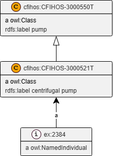
The separation mirrors the layered architecture described in the Handbook, where the functional specification and the physical realization occupy distinct lifecycle zones:
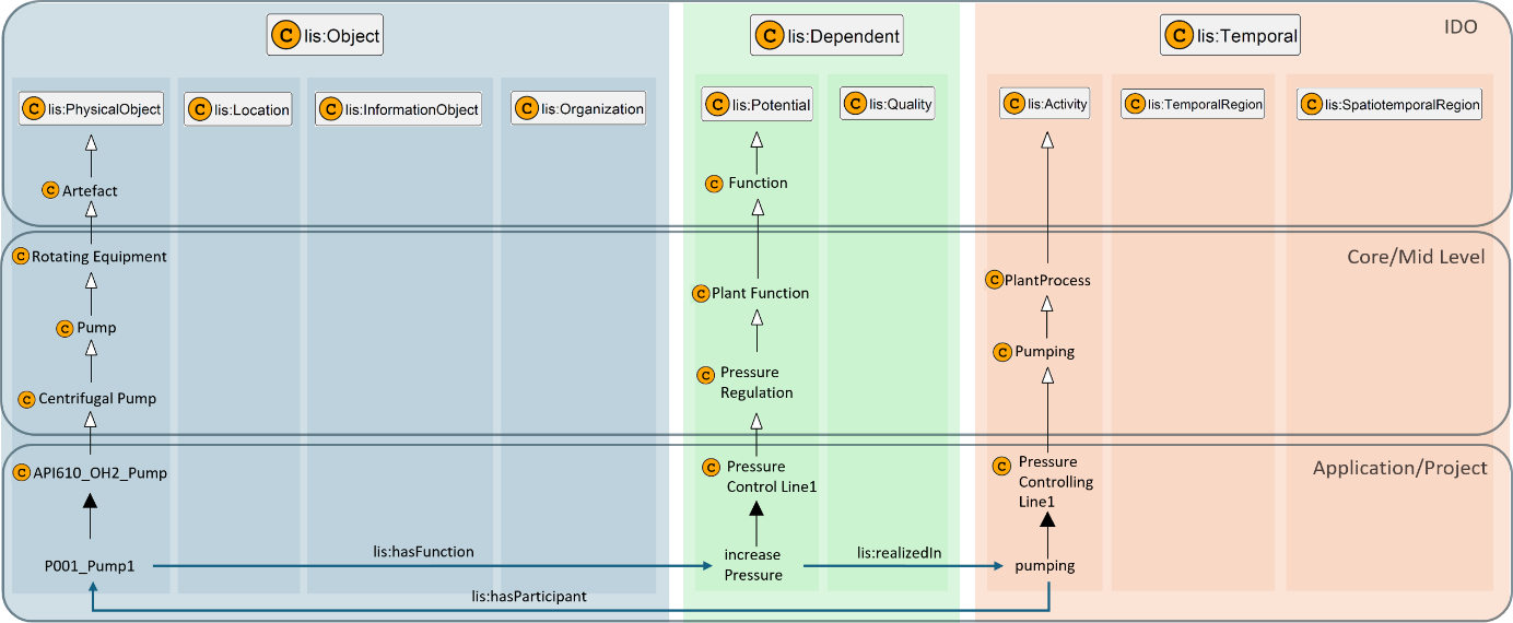
In IDO terms, CFIHOS-30000521T individuals belong to the specified plant world, while CFIHOS-30000521E individuals belong to the Actual asset world. The cfihos:isFulFilledBy property bridges the two, stating that a specific piece of physical equipment fulfills the functional requirements of a given tag.
Worked example 1 — Dependent quantifiable property¶
Scenario: A centrifugal pump (ex:2384) has an upper limit design pressure of 15 bar. This is a dependent quantifiable property: it is an intrinsic quality of the object, expressed as a numeric datum with a unit of measure.
Instance data (Turtle)¶
@prefix owl:    <http://www.w3.org/2002/07/owl#> .
@prefix rdf:    <http://www.w3.org/1999/02/22-rdf-syntax-ns#> .
@prefix rdfs:   <http://www.w3.org/2000/01/rdf-schema#> .
@prefix xsd:    <http://www.w3.org/2001/XMLSchema#> .
@prefix lis:    <http://rds.posccaesar.org/ontology/lis14/rdl/> .
@prefix unit:   <http://qudt.org/vocab/unit/> .
@prefix cfihos: <http://data.cfihos.org/rdl/> .
@prefix ex:     <http://example.com/> .

### Classes
cfihos:CFIHOS-30000521T a owl:Class ;
    rdfs:label "centrifugal pump" .

cfihos:CFIHOS-40000200 a owl:Class ;
    rdfs:label "upper limit design pressure" .

cfihos:RealMeasureTypeDatum a owl:Class ;
    rdfs:label "RealMeasureTypeDatum" .

### Individuals
ex:2384 a owl:NamedIndividual ;
    a cfihos:CFIHOS-30000521T ;
    lis:hasQuality ex:8453 .

ex:8453 a owl:NamedIndividual ;
    a cfihos:CFIHOS-40000200 ;
    lis:qualityQuantifiedAs ex:7533 .

ex:7533 a owl:NamedIndividual ;
    a cfihos:RealMeasureTypeDatum ;
    lis:datumValue "15"^^xsd:decimal ;
    lis:datumUOM unit:BAR .
Pattern walkthrough¶
-
ex:2384is an individual of classcfihos:CFIHOS-30000521T(centrifugal pump — tag lifecycle dataset). -
lis:hasQualitylinks the pump to a quality individualex:8453. -
ex:8453is typed ascfihos:CFIHOS-40000200(upper limit design pressure). -
lis:qualityQuantifiedAslinks the quality to a datum individualex:7533. -
ex:7533holds the numeric value (15) and unit (unit:BAR), typed ascfihos:RealMeasureTypeDatum.
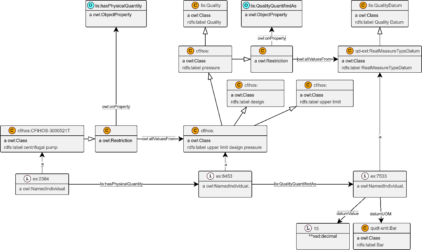
This pattern is consistent with the unified property reification model described in the Handbook: the quality node (ex:8453) is a first-class entity that can carry additional metadata such as data maturity, source system reference, or lifecycle stage without changing the structure of the triple.
Worked example 2 — Dependent property with property aspect¶
Scenario: A centrifugal pump has a design pressure property, where "design" qualifies the scope of the measurement (as opposed to "operating", "maximum", etc.).
Property aspects are applied using cfihos:hasPropertyAspect. In this example, the aspect belongs to cfihos:ScopeAspect.
Instance data (Turtle)¶
@prefix owl:    <http://www.w3.org/2002/07/owl#> .
@prefix rdfs:   <http://www.w3.org/2000/01/rdf-schema#> .
@prefix xsd:    <http://www.w3.org/2001/XMLSchema#> .
@prefix lis:    <http://rds.posccaesar.org/ontology/lis14/rdl/> .
@prefix unit:   <http://qudt.org/vocab/unit/> .
@prefix cfihos: <http://data.cfihos.org/rdl/> .
@prefix ex:     <http://example.com/> .

### Classes
cfihos:CFIHOS-30000521E a owl:Class ;
    rdfs:label "centrifugal pump (equipment)" .

cfihos:CFIHOS-xxxx1 a owl:Class ;
    rdfs:label "design pressure" ;
    cfihos:hasPropertyAspect cfihos:CFIHOS-xxxx3 .

cfihos:CFIHOS-xxxx2 a owl:Class ;
    rdfs:label "pressure" .

cfihos:CFIHOS-xxxx3 a owl:Class ;
    rdfs:subClassOf cfihos:ScopeAspect ;
    rdfs:label "design" .

cfihos:ScopeAspect a owl:Class ;
    rdfs:label "ScopeAspect" .

cfihos:RealMeasureTypeDatum a owl:Class ;
    rdfs:label "RealMeasureTypeDatum" .

### Individuals
ex:2384 a owl:NamedIndividual ;
    a cfihos:CFIHOS-30000521E ;
    lis:hasQuality ex:8453 .

ex:8453 a owl:NamedIndividual ;
    a cfihos:CFIHOS-xxxx1 ;
    lis:qualityQuantifiedAs ex:7533 .

ex:7533 a owl:NamedIndividual ;
    a cfihos:RealMeasureTypeDatum ;
    lis:datumValue "10.0"^^xsd:decimal ;
    lis:datumUOM unit:BAR .
Pattern walkthrough¶
The class cfihos:CFIHOS-xxxx1 ("design pressure") is a subclass of pressure (cfihos:CFIHOS-xxxx2) qualified by a ScopeAspect individual. The property aspect (cfihos:CFIHOS-xxxx3) is attached at the class level via cfihos:hasPropertyAspect, not on individual instances. This means that any individual of type "design pressure" automatically inherits the "design" scope qualification through its class definition.
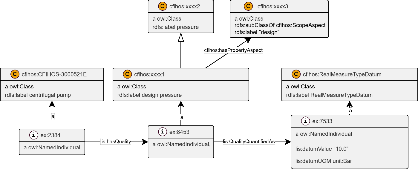
The use of ScopeAspect (alongside RangeAspect, PlaceAspect, FunctionAspect, and ContextAspect) allows CFIHOS to reduce the total number of named property classes significantly: instead of defining separate classes for "design pressure", "operating pressure", and "maximum pressure", a single pressure class is combined with the appropriate scope aspect. See the property-aspects section of the Handbook for the full PropertyAspect taxonomy.
Worked example 3 — Dependent object property: material¶
Scenario: A pipe (ex:5384) has body material austenitic stainless steel.
This is a dependent object property: the datum is not a numeric measure but a reference to a class from a controlled vocabulary. The datum type cfihos:ClassReferenceTypeDatum holds a pointer to the class cfihos:CFIHOS-60000209 (austenitic stainless steel).
Instance data (Turtle)¶
@prefix owl:    <http://www.w3.org/2002/07/owl#> .
@prefix rdfs:   <http://www.w3.org/2000/01/rdf-schema#> .
@prefix lis:    <http://rds.posccaesar.org/ontology/lis14/rdl/> .
@prefix cfihos: <http://data.cfihos.org/rdl/> .
@prefix ex:     <http://example.com/> .

### Classes
cfihos:CFIHOS-30000496T a owl:Class ;
    rdfs:label "pipe" .

cfihos:CFIHOS-40000223 a owl:Class ;
    rdfs:label "material" .

cfihos:ClassReferenceTypeDatum a owl:Class ;
    rdfs:label "ClassReferenceTypeDatum" .

cfihos:CFIHOS-60000209 a owl:Class ;
    rdfs:label "austenitic stainless steel" .

### Individuals
ex:5384 a owl:NamedIndividual ;
    a cfihos:CFIHOS-30000496T ;
    lis:hasQuality ex:7329 .

ex:7329 a owl:NamedIndividual ;
    a cfihos:CFIHOS-40000223 ;
    lis:qualityQuantifiedAs ex:6422 .

ex:6422 a owl:NamedIndividual ;
    a cfihos:ClassReferenceTypeDatum ;
    lis:hasValue cfihos:CFIHOS-60000209 .
Pattern walkthrough¶
The difference from the quantifiable case is that ex:6422 is typed cfihos:ClassReferenceTypeDatum and uses lis:hasValue to point to a class URI rather than a literal value with a unit. This keeps the property structure uniform: all properties go through lis:hasQuality → quality node → lis:qualityQuantifiedAs → datum node, regardless of whether the datum is a number, a string, or a class reference.
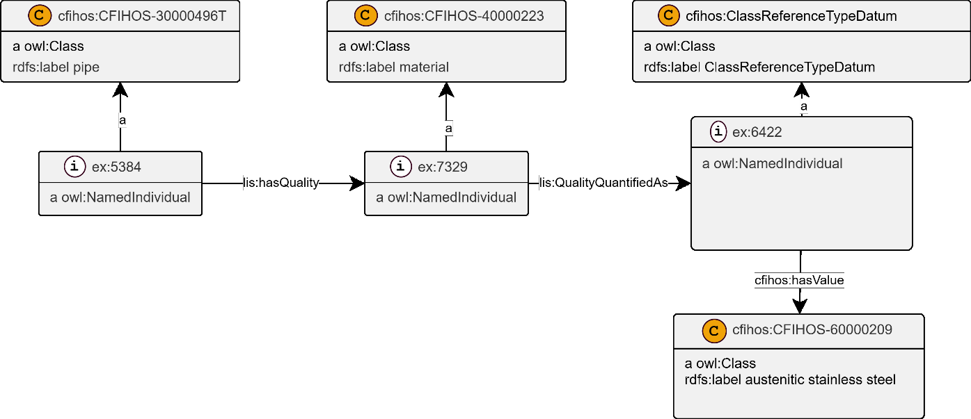
Worked example 4 — Assigned property: tag name¶
Scenario: A centrifugal pump (tag dataset, ex:2384) carries the tag name "11P-101".
Tag name is an assigned property: it does not describe an intrinsic quality of the object but a human-assigned designation. CFIHOS models assigned properties through cfihos:hasAssigned and a separate cfihos:AssignedProperty hierarchy, distinct from the lis:hasQuality chain used for dependent properties.
Instance data (Turtle)¶
@prefix owl:    <http://www.w3.org/2002/07/owl#> .
@prefix rdfs:   <http://www.w3.org/2000/01/rdf-schema#> .
@prefix lis:    <http://rds.posccaesar.org/ontology/lis14/rdl/> .
@prefix cfihos: <http://data.cfihos.org/rdl/> .
@prefix ex:     <http://example.com/> .

### Classes
cfihos:CFIHOS-30000521T a owl:Class ;
    rdfs:label "centrifugal pump" .

cfihos:CFIHOS-10000166 a owl:Class ;
    rdfs:label "tag name" .

cfihos:NonTranslatableStringTypeDatum a owl:Class ;
    rdfs:label "NonTranslatableStringTypeDatum" .

### Individuals
ex:2384 a owl:NamedIndividual ;
    a cfihos:CFIHOS-30000521T ;
    cfihos:hasAssigned ex:5206 .

ex:5206 a owl:NamedIndividual ;
    a cfihos:CFIHOS-10000166 ;
    cfihos:hasDatum ex:7433 .

ex:7433 a owl:NamedIndividual ;
    a cfihos:NonTranslatableStringTypeDatum ;
    lis:datumValue "11P-101"^^xsd:string .
Pattern walkthrough¶
-
The pump individual (
ex:2384) usescfihos:hasAssigned— notlis:hasQuality— to link to the assigned property node. -
ex:5206is typed ascfihos:CFIHOS-10000166(tag name) and usescfihos:hasDatumto point to the string datum. -
ex:7433is typedcfihos:NonTranslatableStringTypeDatumbecause a tag name is a fixed string that must not be translated across languages.
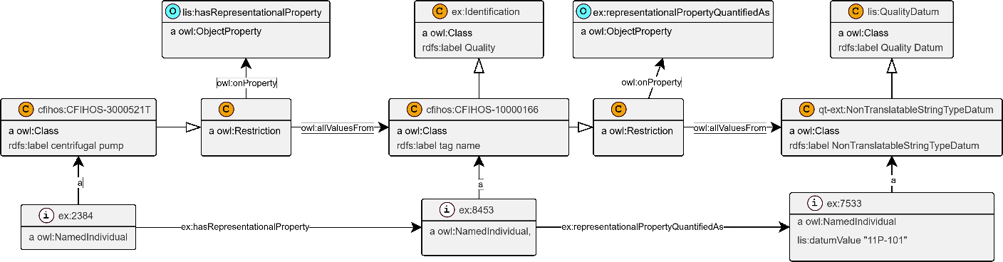
The structural separation between dependent properties (lis:hasQuality) and assigned properties (cfihos:hasAssigned) is enforced at the class level through OWL restrictions. Both paths nevertheless reify the property as a first-class individual node, enabling metadata — such as data maturity or lifecycle stage — to be attached uniformly regardless of property type.
Worked example 5 — Assigned property: manufacturer¶
Scenario: A centrifugal pump (tag dataset, ex:2384) is manufactured by the company BLOG.
Manufacturer is a reference property: it points to an external governed entity (a company record in a master data system). The datum type cfihos:ObjectReferenceTypeDatum holds the reference.
Instance data (Turtle)¶
@prefix owl:    <http://www.w3.org/2002/07/owl#> .
@prefix rdfs:   <http://www.w3.org/2000/01/rdf-schema#> .
@prefix lis:    <http://rds.posccaesar.org/ontology/lis14/rdl/> .
@prefix cfihos: <http://data.cfihos.org/rdl/> .
@prefix ex:     <http://example.com/> .

### Classes
cfihos:CFIHOS-30000521T a owl:Class ;
    rdfs:label "centrifugal pump" .

cfihos:CFIHOS-10000036 a owl:Class ;
    rdfs:label "manufacturer" .

cfihos:ObjectReferenceTypeDatum a owl:Class ;
    rdfs:label "ObjectReferenceTypeDatum" .

### Individuals
ex:2384 a owl:NamedIndividual ;
    a cfihos:CFIHOS-30000521T ;
    cfihos:hasAssigned ex:7342 .

ex:7342 a owl:NamedIndividual ;
    a cfihos:CFIHOS-10000036 ;
    cfihos:hasDatum ex:7422 .

ex:7422 a owl:NamedIndividual ;
    a cfihos:ObjectReferenceTypeDatum ;
    cfihos:hasValue ex:5389 .

### Reference individual (company record)
ex:5389 a owl:NamedIndividual ;
    a cfihos:COMPANY ;
    cfihos:companyName "BLOG"^^xsd:string .
Pattern walkthrough¶
The manufacturer example follows the same assigned-property structure as the tag name. The distinction is the datum type: cfihos:ObjectReferenceTypeDatum wraps a pointer to a company individual rather than a string. It uses cfihos:hasValue — rather than lis:hasValue used by cfihos:ClassReferenceTypeDatum in Example 3 — because the reference target is a named individual rather than an OWL class URI. If the company already exists in the knowledge graph, ex:5389 resolves to its existing record; if not, a new company individual is created and linked.
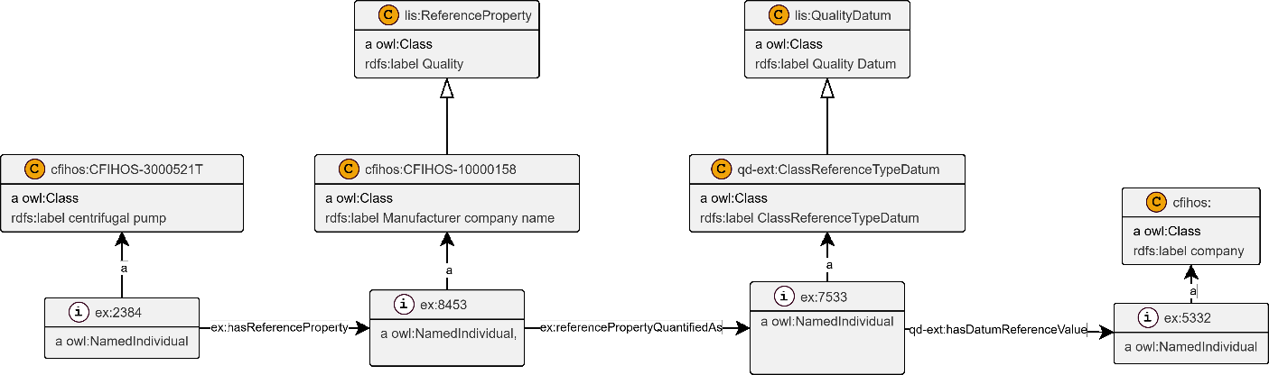
OWL class restrictions and class profiles¶
CFIHOS class restrictions constrain which properties — and which datum types — are allowable for a given class. Each permissible property is represented by an anonymous owl:Restriction declared as a rdfs:subClassOf the class it applies to.
The example below shows restrictions for the power cable class (cfihos:CFIHOS-30000360T), constraining the quality type to "length" and the datum type to cfihos:RealMeasureTypeDatum:
@prefix owl:    <http://www.w3.org/2002/07/owl#> .
@prefix rdfs:   <http://www.w3.org/2000/01/rdf-schema#> .
@prefix lis:    <http://rds.posccaesar.org/ontology/lis14/rdl/> .
@prefix cfihos: <http://data.cfihos.org/rdl/> .

cfihos:CFIHOS-30000360T a owl:Class ;
    rdfs:label "power cable" .

cfihos:CFIHOS-40000201 a owl:Class ;
    rdfs:label "length" .

cfihos:RealMeasureTypeDatum a owl:Class ;
    rdfs:label "RealMeasureTypeDatum" ;
    rdfs:subClassOf lis:QualityDatum .

# Restriction 1: a power cable may only have "length" as a quality.
cfihos:CFIHOS-30000360T rdfs:subClassOf [
    a owl:Restriction ;
    owl:onProperty lis:hasQuality ;
    owl:allValuesFrom cfihos:CFIHOS-40000201
] .

# Restriction 2: a "length" quality may only be quantified as a RealMeasureTypeDatum.
cfihos:CFIHOS-40000201 rdfs:subClassOf [
    a owl:Restriction ;
    owl:onProperty lis:qualityQuantifiedAs ;
    owl:allValuesFrom cfihos:RealMeasureTypeDatum
] .
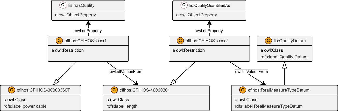
In CFIHOS, the centrifugal pump tag class (CFIHOS-30000521T) has approximately 100 permissible properties defined through this restriction mechanism, while the equipment class (CFIHOS-30000521E) has approximately 250. Only about 1% of properties appear under the same name in both lifecycle datasets. This separation is enforced through distinct owl:allValuesFrom restrictions declared on the tag and equipment subclasses respectively, preventing tag-only properties from being incorrectly applied to equipment individuals and vice versa.
Lifecycle-tagged property values¶
Property values can be tagged with a lifecycle stage to indicate in which lifecycle context a value was recorded or applies. This uses cfihos:hasLifecycleStage, as described in the Handbook section on lifecycle stage grouping for instance data.
The following example shows the pump tag (ex:2384) and equipment (ex:4387) individuals each assigned to their respective lifecycle stage, and linked via cfihos:isFulFilledBy:
@prefix owl:    <http://www.w3.org/2002/07/owl#> .
@prefix rdfs:   <http://www.w3.org/2000/01/rdf-schema#> .
@prefix cfihos: <http://data.cfihos.org/rdl/> .
@prefix ex:     <http://example.com/> .

### Lifecycle stage classes
cfihos:TagLifecycleStage a owl:Class ;
    rdfs:label "Tag lifecycle stage" .

cfihos:EquipmentLifecycleStage a owl:Class ;
    rdfs:label "Equipment lifecycle stage" .

### Tag individual (specification)
ex:2384 a owl:NamedIndividual ;
    a cfihos:CFIHOS-30000521T ;
    cfihos:hasLifecycleStage cfihos:TagLifecycleStage ;
    cfihos:isFulFilledBy ex:4387 .

### Equipment individual (realization)
ex:4387 a owl:NamedIndividual ;
    a cfihos:CFIHOS-30000521E ;
    cfihos:hasLifecycleStage cfihos:EquipmentLifecycleStage .
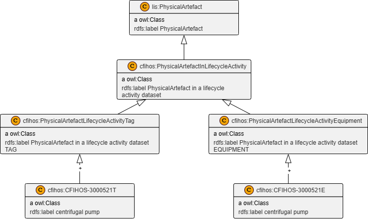
The cfihos:isFulFilledBy link is the CFIHOS equivalent of the IDO lis:implements / lis:implementedBy relation: it bridges the specified (TAG) plant item to the actual (EQUIPMENT) physical device. This enables cross-lifecycle queries — for example, retrieving the actual operating pressure of the equipment that fulfills a given tag specification — without merging the two datasets.
Open issues¶
The following issues in this use case are tracked in the Handbook’s open-issues register.
Placeholder IDs for new property and restriction classes
: Several property and restriction classes in the worked examples use placeholder URIs (e.g., cfihos:CFIHOS-xxxx1, cfihos:CFIHOS-xxxx2). These will be replaced with official CFIHOS RDL identifiers once the CFIHOS Semantics review process assigns permanent IDs.
cfihos:hasAssigned and cfihos:hasDatum property status
: The cfihos:hasAssigned and cfihos:hasDatum properties are CFIHOS extensions to IDO, not part of the IDO core. Their alignment with the IDO lis:hasQuality / lis:qualityQuantifiedAs chain — and whether they should be declared as sub-properties of IDO properties — is under discussion with the IDO core team.
Single-parent vs. dual-parent inheritance for tag and equipment classes
: Whether cfihos:CFIHOS-30000521T and cfihos:CFIHOS-30000521E should subclass only cfihos:PhysicalArtefactInLifecycleActivity (single parent) or also directly subclass the generic CFIHOS plant-object class (dual parent) is an open design question with implications for reasoner performance and class-profile inheritance.
cfihos:isFulFilledBy alignment with lis:implementedBy
: Whether isFulFilledBy should be declared owl:equivalentProperty to lis:implementedBy, or treated as a more specialized sub-property, requires agreement between CFIHOS and IDO governance bodies.
cfihos:RealMeasureTypeDatum vs. lis:RealMeasureTypeDatum
: The CFIHOS guide introduces cfihos:RealMeasureTypeDatum as a subclass of lis:QualityDatum. Whether this class is already present in IDO under a different URI, or whether lis:ScalarQuantityDatum subsumes its role, requires clarification with the IDO core team.
Process Plant Digital Twin use case¶
Torbjörn Holm
::: {wrapper="1" role="lead"} Extended Technical Report on Semantic Interoperability, Lifecycle Digital Twins, Knowledge Graphs, and Industrial Operational Integration :::
Introduction¶
UC 2.9 "Process Plant Digital Twin" is an Arrowhead fPVN use case addressing semantic interoperability, industrial knowledge graphs, lifecycle information management, and cross-domain engineering integration for process industry facilities. It connects industrial information from heterogeneous operational systems into a coherent, semantically accessible environment spanning the full plant lifecycle. It addresses UC-06 (DEXPI/CFIHOS/STEP alignment for handover) and UC-08 (operations and condition monitoring) from the Handbook’s motivating scenarios.
The environment integrates automation systems, enterprise maintenance, engineering tools, lifecycle models, semantic technologies, and 3D plant representations. The demonstration is grounded in real engineering configuration, lifecycle data, plant topology, and operational data from a Stora Enso paper mill in Sweden.
The aim is a semantically connected knowledge environment — one in which engineering intent, operational context, lifecycle history, and maintenance activities remain consistently understandable across all contributing systems — rather than simple data exchange between them.
Objectives of the Use Case¶
The primary objective of UC 2.9 is to demonstrate how semantic interoperability can enable operational and lifecycle continuity across traditionally isolated industrial systems.
In conventional industrial environments, information related to process plants is fragmented across multiple systems including automation systems, enterprise systems, engineering repositories, lifecycle systems, and maintenance environments, as illustrated in Figure 45.
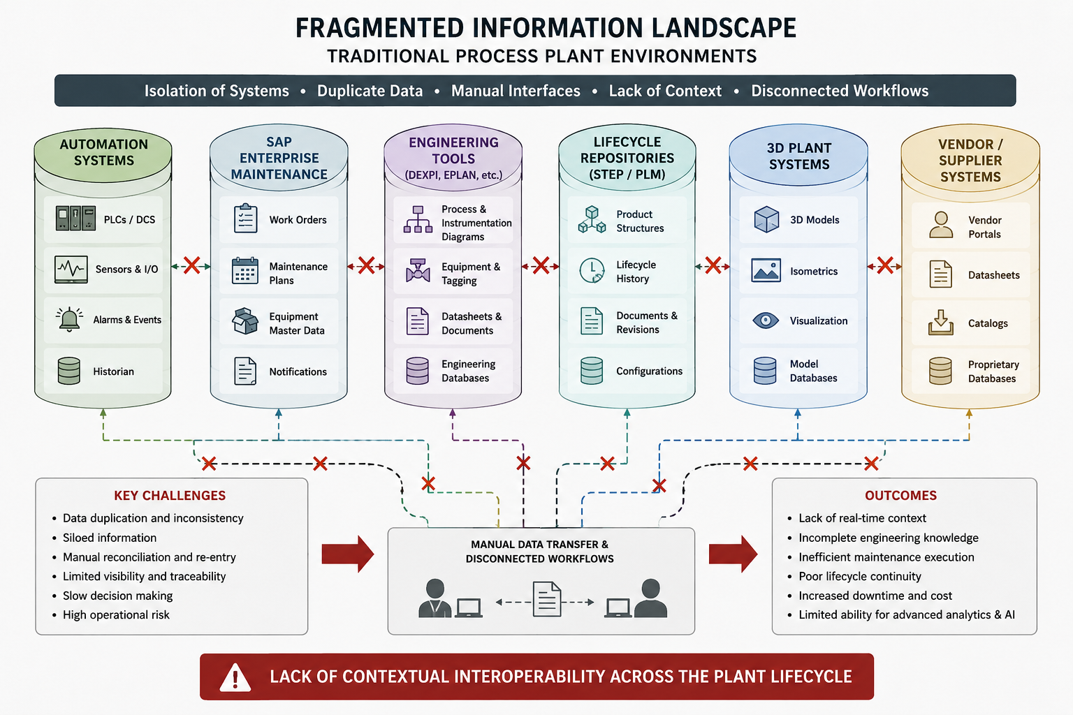
The fragmented landscape encompasses six distinct system categories: (1) Automation Systems (PLC/DCS/SCADA, sensors, historian), (2) SAP Enterprise Maintenance (work orders, PM notifications, equipment master data), (3) Engineering Tools (DEXPI, P&IDs, datasheets), (4) Lifecycle Repositories (STEP/PLM, product structures, configurations), (5) 3D Plant Systems (plant models, isometrics), and (6) Vendor/Supplier Systems (portals, catalogs, proprietary databases). The operational consequences are data duplication and inconsistency, manual reconciliation and re-entry, limited visibility and traceability, slow decision-making, and elevated operational risk — ultimately resulting in incomplete engineering knowledge, inefficient maintenance execution, and poor lifecycle continuity.
UC 2.9 addresses this challenge by establishing a semantically connected Digital Twin environment where:
-
Systems share contextual understanding
-
Functional and physical relationships are connected
-
Lifecycle knowledge is preserved over time
-
Engineering and operational domains become interoperable
-
Information can be traversed across domains
-
Historical realization chains remain accessible
-
Maintenance decisions become knowledge-driven
The use case therefore demonstrates both technical interoperability and operational value creation.
Architectural Principles¶
The architecture used in UC 2.9 is based on federated interoperability principles rather than centralized monolithic system integration. Instead of replacing existing industrial systems, the architecture semantically connects them using shared identities, ontologies, Knowledge Graph technologies, lifecycle structures, and semantic contextualization (Figure 46). The architectural principles include federated interoperability; Knowledge Graph-centric integration; shared semantic identities; lifecycle continuity; separation of functional and physical perspectives; cross-domain contextualization; and incremental interoperability adoption.
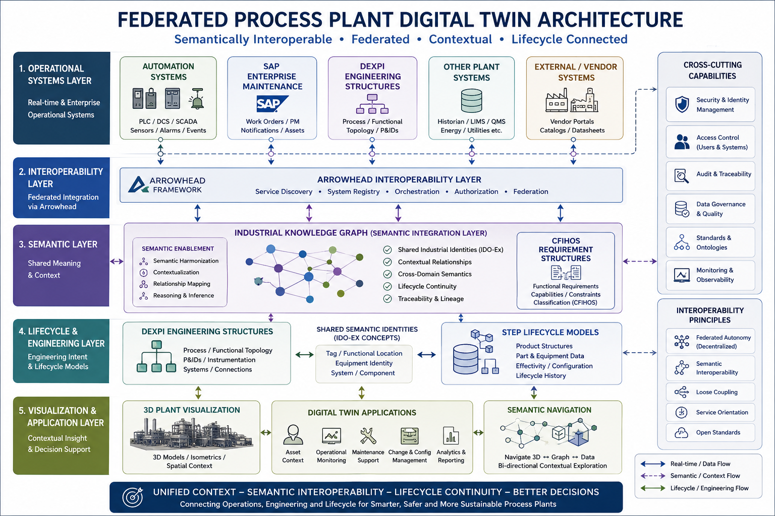
The architecture is structured across five layers: (1) The Operational Systems Layer integrates real-time sources: automation systems (PLC/DCS/SCADA), SAP enterprise maintenance, DEXPI engineering structures, plant historian and utilities, and external vendor portals. (2) The Interoperability Layer is provided by the Arrowhead Framework, offering service discovery, system registry, orchestration, authorization, and federation services. (3) The Semantic Layer hosts the Industrial Knowledge Graph, which provides semantic harmonization, contextualization, relationship mapping, reasoning and inference, together with CFIHOS-based requirement structures and shared IDO-Ex identities. (4) The Lifecycle & Engineering Layer holds DEXPI engineering structures, shared IDO-Ex semantic identities, and STEP lifecycle models including product structures, effectivity, configuration, and lifecycle history. (5) The Visualization & Application Layer provides 3D plant visualization, digital twin applications (asset context, operational monitoring, maintenance support, change management, analytics), and bidirectional semantic navigation (3D ↔ graph ↔ data).
Cross-cutting capabilities span all layers: security and identity management, access control, audit and traceability, data governance and quality, standards and ontologies governance, and system monitoring and observability. The architecture rests on five interoperability principles: Federated Autonomy (decentralized governance), Semantic Interoperability, Loose Coupling, Service Orientation, and adherence to Open Standards.
The solution therefore enables interoperability without requiring complete redesign of existing operational environments, as shown in Figure 47.
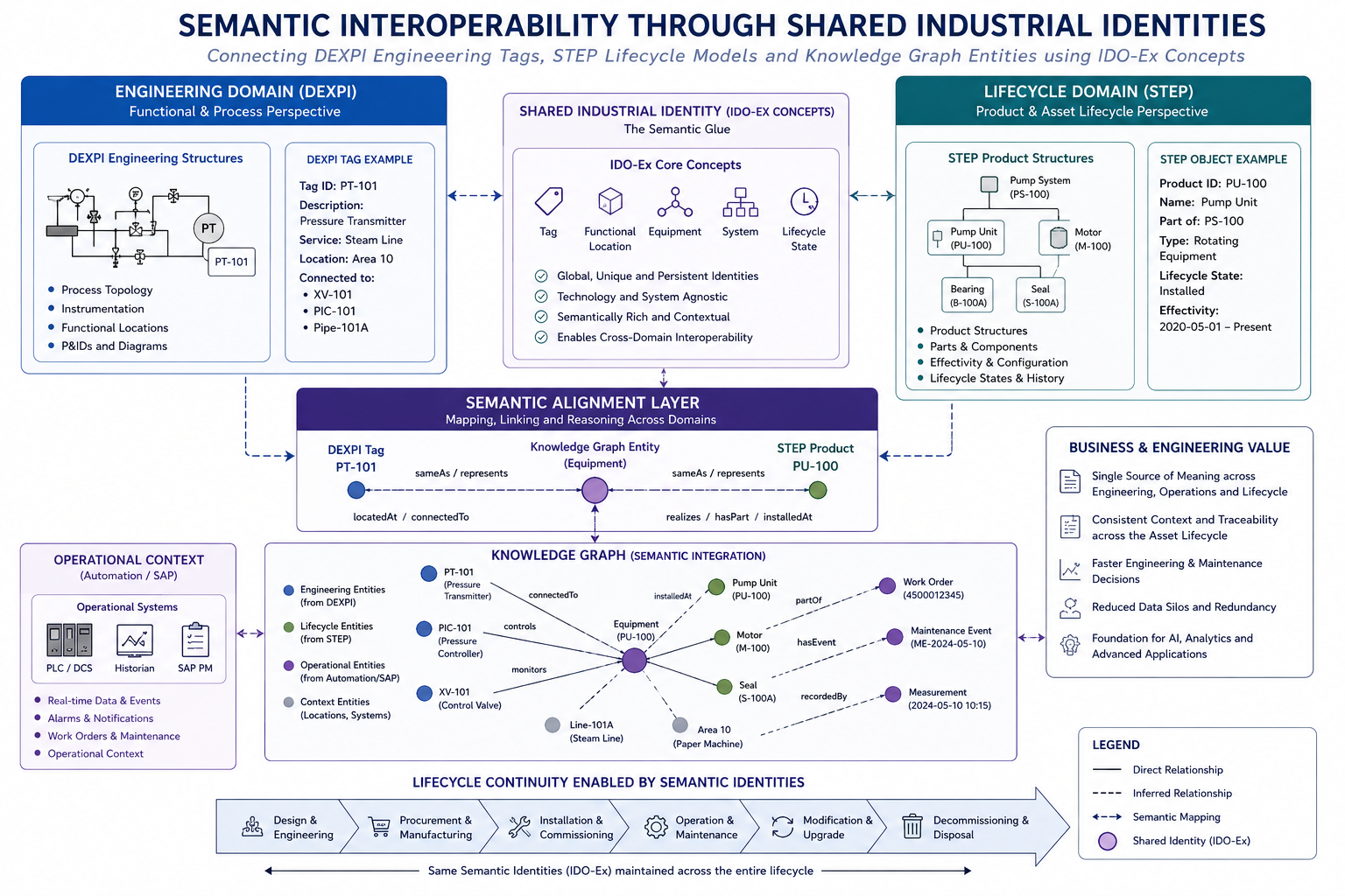
IDO-Ex (IDO Extension) is a lightweight set of plant identity classes defined as subclasses of lis:Object, developed within this use case to provide stable, system-agnostic cross-domain anchors on top of the IDO upper ontology. The shared identity layer is built on five IDO-Ex core concepts: Tag, Functional Location, Equipment, System, and Lifecycle State. These identities are global, unique, and persistent; they are technology- and system-agnostic; and they provide a semantically rich bridge that enables cross-domain interoperability. As a concrete example, a DEXPI engineering tag (e.g., PT-101, a Pressure Transmitter in Area 10) is linked to the corresponding STEP product object (e.g., PU-100, a Pump Unit) through a shared IDO-Ex Equipment concept, with relationships of type sameAs/represents, locatedAt/connectedTo, and realizes/hasPart/installedAt maintained in the Knowledge Graph. The same semantic identities are preserved across the full lifecycle — from Design & Engineering through Procurement, Installation, Operation & Maintenance, Modification, and eventual Decommissioning.
Formal IDO Representation of the Digital Twin¶
In IDO terms, the Digital Twin is formally modeled as a lis:Object representing the physical asset. Multiple ido:Representation instances are attached to this object, each corresponding to a distinct domain view:
-
a design representation — grounded in the STEP product model
-
an operational representation — grounded in the DEXPI functional and P&ID structure
-
an automation representation — grounded in the AFO/OPC UA cyber-physical model
-
an asset management representation — grounded in CFIHOS and the SAP equipment master
Each representation is aligned to the standard-specific class hierarchy of its domain while remaining semantically anchored to the shared lis:Object. This multi-representation structure is what allows systems from different domains to refer to the same physical asset without requiring a single merged data model. The IDO-Ex identity concepts (Tag, Functional Location, Equipment, etc.) act as persistent anchors that survive lifecycle changes and system replacements.
Minimal Class Alignment Principle¶
A core design principle of the architecture is that only a small, carefully selected subset of high-value classes is aligned across standards. In UC 2.9 this subset is: Equipment, Functional Location, Tag, System, and Lifecycle State. This deliberate minimalism prevents unsustainable class-by-class harmonization — major industrial standards such as STEP, IFC, and OPC UA contain thousands of classes, making full cross-standard alignment both unrealistic and unmaintainable. By anchoring alignment at a small set of shared concepts and delegating all domain-specific structure to the respective standard’s own class hierarchy, the architecture remains scalable as standards evolve. Additional alignment classes can be introduced incrementally where business need justifies the governance cost.
Perspective-Based Alignment¶
IDO’s open class hierarchy — where every domain class is a subclass of lis:Object, lis:Dependent, or lis:Temporal — is the architectural feature that makes the multi-representation model work in practice. Rather than requiring a single merged class to represent a pump in DEXPI, STEP, AFO, and SAP simultaneously, IDO allows each domain ontology to subclass lis:Object independently, maintaining its own perspective on the same underlying physical asset:
-
the DEXPI perspective captures the functional and process view (P&ID tag, process connections, instrumentation)
-
the STEP perspective captures the design and lifecycle view (product structure, effectivity, configuration)
-
the AFO/OPC UA perspective captures the cyber-physical view (automation interfaces, real-time services)
-
the CFIHOS/SAP perspective captures the asset management view (classification, maintenance history, requirements)
Each perspective is a legitimate and internally consistent representation of the asset within its originating standard. The shared lis:Object root provides the formal bridge that links them without flattening or merging their distinct structures. This is what allows, for example, a SAP work order to be navigated directly to the corresponding DEXPI functional tag and STEP lifecycle record — all referring to the same physical object — without requiring any of the source systems to change their internal models.
Technologies and Standards Used¶
The Process Plant Digital Twin combines multiple technologies and standards into a semantically integrated interoperability environment (Figure 48). The technologies used include Knowledge Graph technologies; Arrowhead Framework and Ontology; DEXPI engineering structures; STEP and Semantic STEP; IDO-Ex semantic identity alignment; CFIHOS-based requirement structures; SAP enterprise maintenance integration; and 3D plant visualization and topology navigation. For the IDO alignment approach covering DEXPI, STEP, and CFIHOS, see Handbook > Standards alignment.
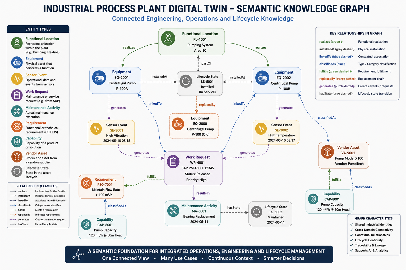
The Industrial Knowledge Graph represents nine entity types: Functional Location, Equipment, Sensor Event, Work Request, Maintenance Activity, Requirement, Capability, Vendor Asset, and Lifecycle State. Entities are connected by eight core relationship types: realizes (functional realization), installedAt (physical installation), linkedTo (contextual association), classifiedAs (categorization), fulfills (requirement fulfillment), replacedBy (replacement chain), generates (event/request generation), and hasState (lifecycle state transition). A representative example from the demonstration: Equipment EQ-2001 (Centrifugal Pump P-100A) realizes Functional Location FL-1001 (Pumping System, Area 10); EQ-2001 generates Sensor Event SE-3001 (High Vibration, 2024-05-10 08:15); SE-3001 generates Work Request WR-4001 (SAP PM 4500012345, Priority: High); WR-4001 results in Maintenance Activity MA-6001 (Bearing Replacement, 2024-05-11).
Together these technologies create a lifecycle-aware interoperability architecture capable of connecting operational, engineering, enterprise, and lifecycle domains (Figure 49).
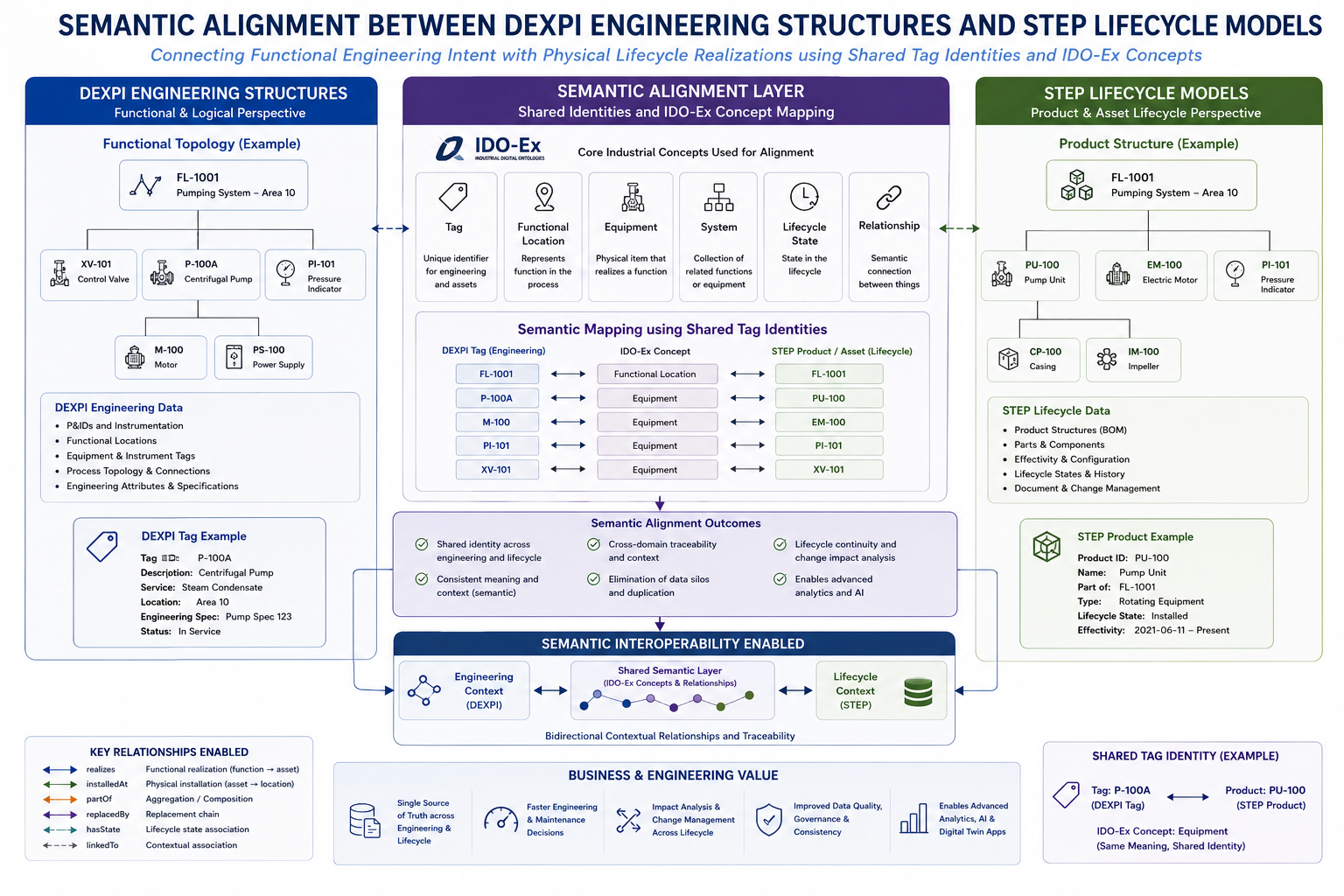
Expanded Capability and Benefit Analysis¶
Improved Operational Context¶
Spatial context: The 3D-integrated Digital Twin environment enables engineers and maintenance personnel to understand where equipment is physically located within the plant and how it relates to surrounding systems. The semantic interoperability architecture enhances this capability by linking Knowledge Graph structures directly to 3D navigation and engineering topology (Figure 50).
When an asset is selected in the 3D view — for example, pump P-100A in Area 10 — the Digital Twin presents a contextual summary panel containing the DEXPI tag, functional location, system assignment, operating status, STEP lifecycle state, manufacturer, model, serial number, installation date, and effectivity period.
Six quick actions are immediately available: Show Neighbors (3D), Show in Graph, View Engineering Data, View Lifecycle History, Create Work Request, and Open in SAP PM. Five lower information panels provide: neighboring assets with physical distances (e.g., XV-101 Control Valve at 3.2 m, P-100B at 5.6 m), a STEP lifecycle history timeline (Manufactured → Installed → Overhaul → Seal Replacement), DEXPI engineering context (P&ID reference, functional and equipment specifications, 3D model file, instrumentation list), CFIHOS requirements and matched capabilities, and associated documents (datasheet, maintenance manual, alignment procedure, work instructions, inspection report).
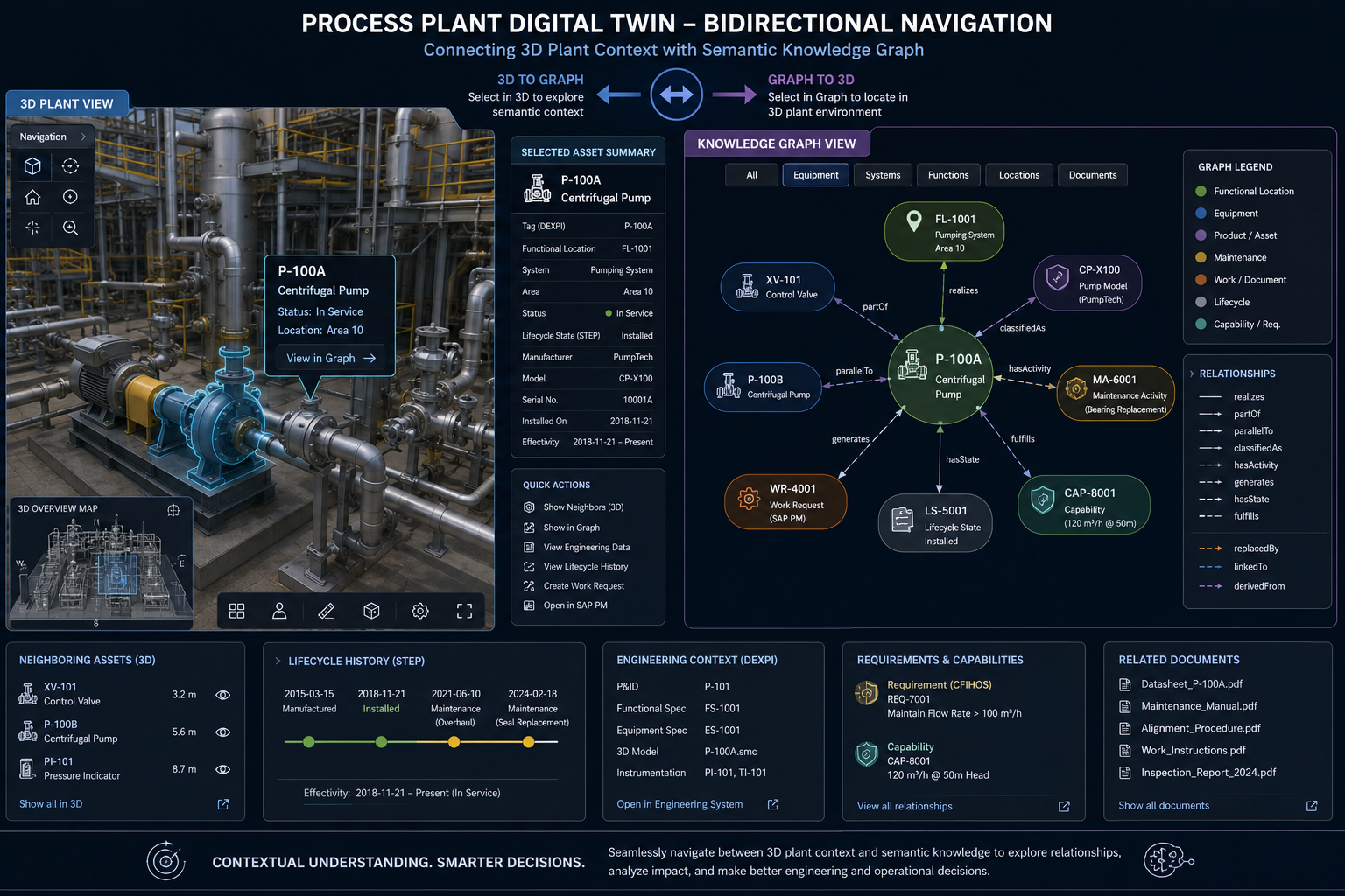
System topology: The Process Plant Digital Twin enhances topology understanding by semantically connecting functional locations, neighboring systems, process structures, and lifecycle information through shared semantic identities and graph relationships.
Lifecycle history: The architecture preserves historical realization chains, installation histories, and effectivity periods. This enables engineering personnel to understand how the plant has evolved over time and enhances operational continuity across maintenance cycles.
Functional relationships: The semantic model connects functional intent with operational context. This enhances the ability to understand why equipment exists, how it contributes to process functionality, and what engineering purpose it fulfills.
Lifecycle Knowledge Preservation¶
Realization history: The Digital Twin preserves historical information about installed equipment and replacement chains. This enhances long-term engineering traceability and allows future maintenance decisions to be based on historical operational knowledge (Figure 51). The demonstration is based on Functional Location FL-1001 (Pumping System – Area 10), whose functional intent — "deliver process fluid from suction to discharge at the required flow, head, and reliability" — remains constant throughout the plant lifetime.
Over nine or more years of operation, four physical realizations have been successively installed and removed: EQ-2000 (Model CP-X100, Serial 10001A, 2015-03-15 to 2018-11-20), EQ-2100 (Model CP-X200, Serial 20015B, 2018-11-21 to 2021-06-10), EQ-2200 (Model CP-X300, Serial 30022C, 2021-06-11 to 2024-02-18), and the current EQ-2300 (Model CP-X300 Plus, Serial 40031D, installed 2024-02-19). Individual maintenance events across the chain include bearing replacements, seal replacements, and impeller replacements, enabling root cause analysis, regulatory and audit compliance, engineering change impact analysis, and long-term reliability planning.
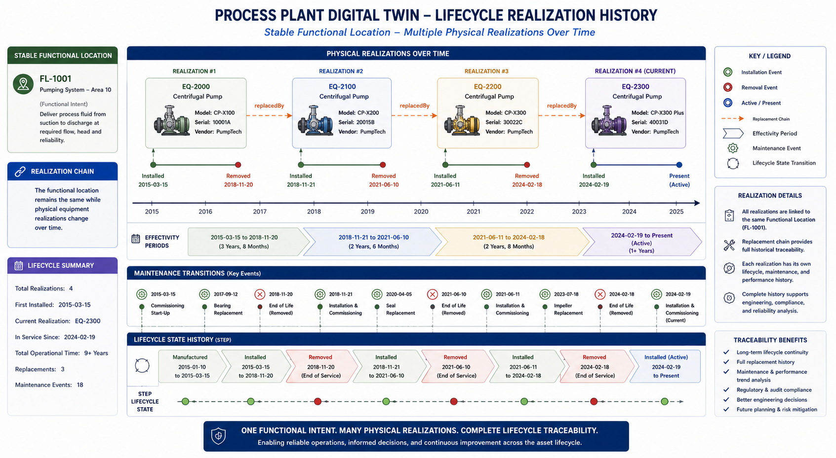
Effectivity chains: Effectivity modeling enables the architecture to represent which physical realization was active during specific operational periods. This capability enhances lifecycle reasoning and maintenance transparency.
Functional continuity: The separation between functional intent and physical realization ensures that engineering meaning remains stable even when physical equipment changes over time (Figure 52). The replacedBy chain — EQ-2000 → EQ-2100 → EQ-2200 → EQ-2300 — is explicitly modeled in the STEP lifecycle representation, with each realization carrying its own installation and removal timestamps, effectivity period, and maintenance history, all anchored to the stable functional location FL-1001. This ensures that the engineering meaning encoded in the functional location is never lost even as the physical equipment evolves across decades of operation.
Engineering relationships: Knowledge Graph technologies preserve semantic relationships between systems, equipment, requirements, and operational context.
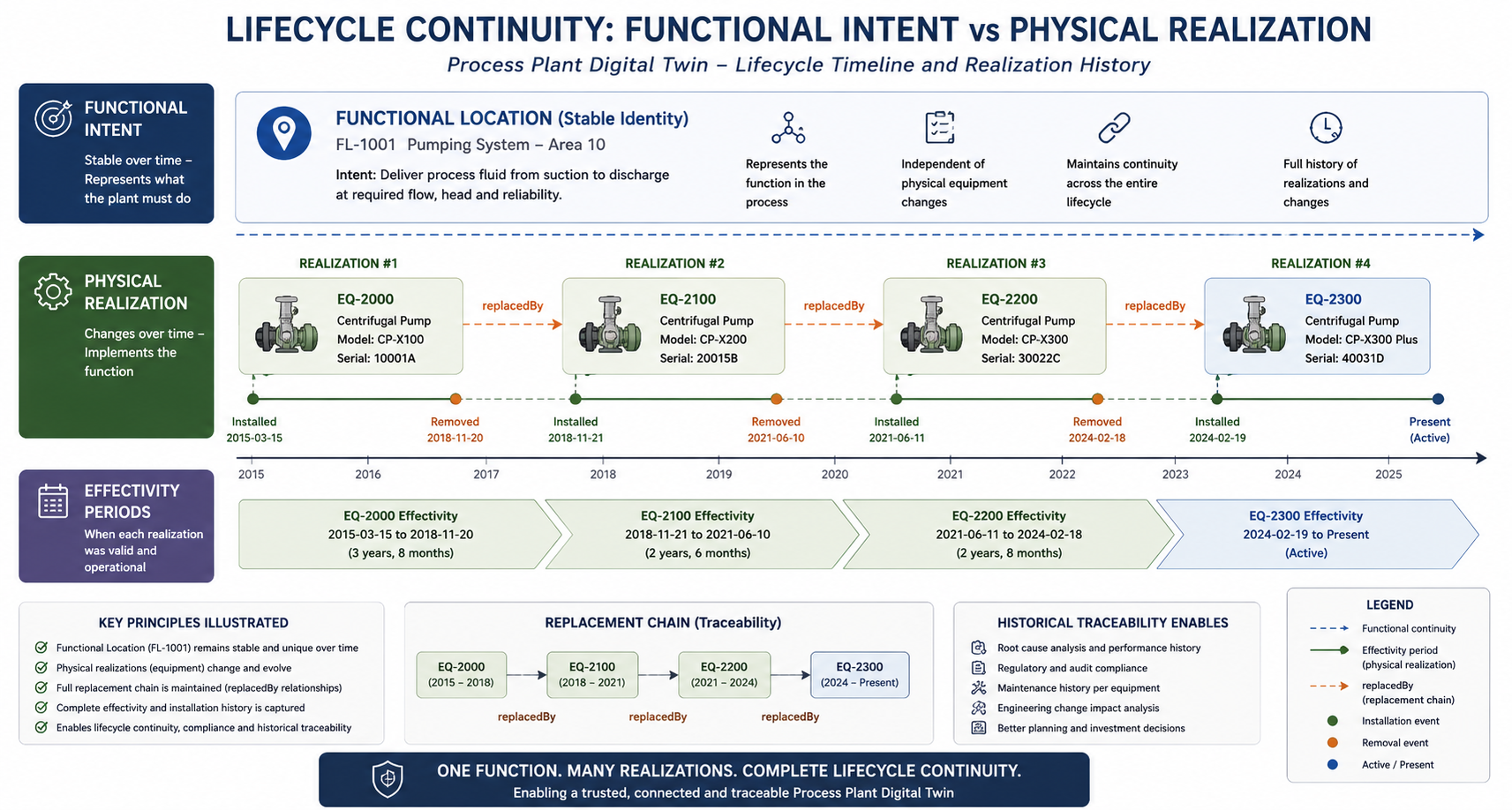
Cross-Domain Interoperability¶
Automation integration: Operational events and sensor readings from automation systems become semantically connected to enterprise and engineering domains.
Enterprise maintenance integration: SAP workflows become visible across engineering and operational systems through semantic interoperability.
Engineering interoperability: DEXPI engineering structures, STEP lifecycle models, and semantic Knowledge Graph representations are aligned using shared semantic identities.
3D and semantic integration: The architecture enables bidirectional navigation between 3D plant representations and semantic graph structures.
Improved Maintenance Decision Support¶
Historical realizations: Maintenance personnel can evaluate previous equipment installations and historical replacement patterns.
Requirement structures: CFIHOS-based semantic requirement models allow engineering requirements to become machine understandable (see Handbook > Alignment with CFIHOS and Use Case: CFIHOS Semantics).
Capability matching: The semantic architecture enables evaluation of vendor equipment capabilities against functional requirements (Figure 53).
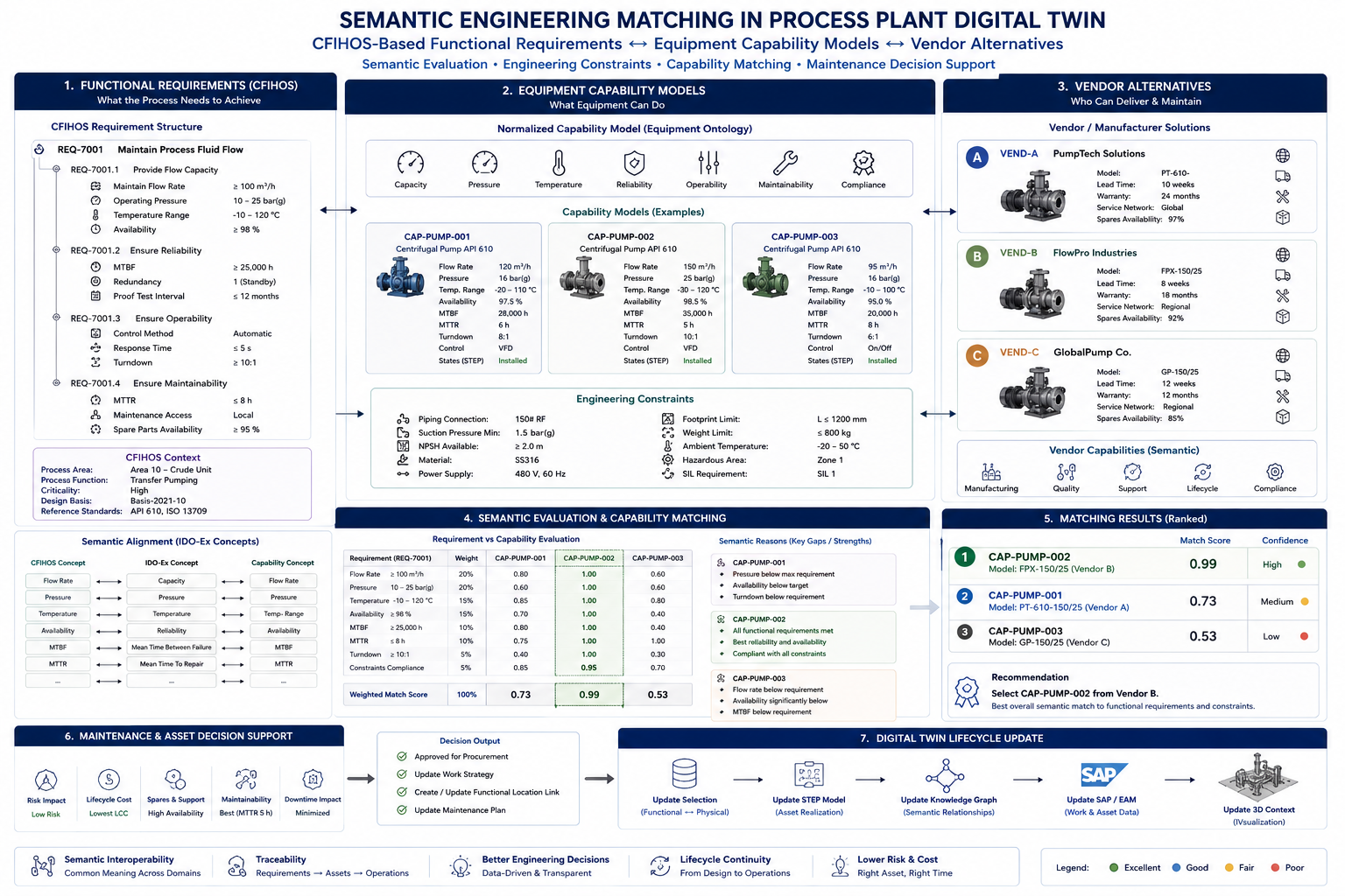
The matching process is structured in four stages. First, the CFIHOS requirement is decomposed into four sub-requirements: REQ-7001.1 (flow capacity: ≥ 100 m³/h flow rate, 10–25 bar(g) operating pressure, −10–120 °C temperature range, ≥ 98 % availability), REQ-7001.2 (reliability: MTBF ≥ 25 000 h, standby redundancy, proof test interval ≤ 12 months), REQ-7001.3 (operability: automatic control, response time ≤ 5 s, turndown ≥ 10:1), and REQ-7001.4 (maintainability: MTTR ≤ 8 h, local access, spare parts availability ≥ 95 %). Engineering constraints include piping class 150# RF, NPSH available ≥ 2.0 m, material SS316, hazardous area Zone 1, and SIL 1 requirement.
Second, equipment capability models are normalized across seven dimensions (Capacity, Pressure, Temperature, Reliability, Operability, Maintainability, Compliance) using the Equipment Ontology. Three candidate models are evaluated: CAP-PUMP-001 (120 m³/h, 16 bar, MTBF 28 000 h, MTTR 6 h), CAP-PUMP-002 (150 m³/h, 25 bar, MTBF 35 000 h, MTTR 5 h), and CAP-PUMP-003 (95 m³/h, 16 bar, MTBF 20 000 h, MTTR 8 h).
Third, a weighted semantic evaluation scores each model across eight criteria (Flow Rate 20 %, Pressure 20 %, Temperature 15 %, Availability 15 %, MTBF 10 %, MTTR 10 %, Turndown 5 %, Constraints Compliance 5 %), yielding weighted match scores of 0.73, 0.99, and 0.53 respectively. CAP-PUMP-002 (Vendor B FlowPro Industries, Model FPX-150/25) is ranked first as it meets all functional requirements and constraints; CAP-PUMP-001 (Vendor A PumpTech Solutions, Model PT-610) is ranked second due to pressure and availability shortfalls; CAP-PUMP-003 (Vendor C GlobalPump Co.) is ranked third due to insufficient flow rate and MTBF.
Fourth, the decision output triggers: approval for procurement, update of the work strategy, creation or update of the Functional Location link, and update of the maintenance plan. The Digital Twin is then updated in five sequential steps: selection update (functional ↔ physical), STEP model update (asset realization), Knowledge Graph update (semantic relationships), SAP/EAM update (work and asset data), and 3D context refresh.
Availability and planning: Enterprise maintenance workflows and lifecycle structures are semantically connected.
Foundation for Industrial AI¶
Semantic grounding: AI systems require structured contextual information to perform meaningful reasoning (Figure 54).
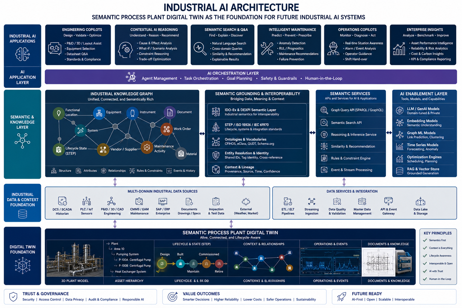
Lifecycle awareness: The Digital Twin preserves lifecycle continuity and operational history.
Cross-domain relationships: The semantic interoperability environment enables AI systems to traverse operational, engineering, and enterprise relationships.
Engineering copilots: The semantically connected architecture creates a foundation for future engineering assistants and intelligent industrial support systems (Figure 55).
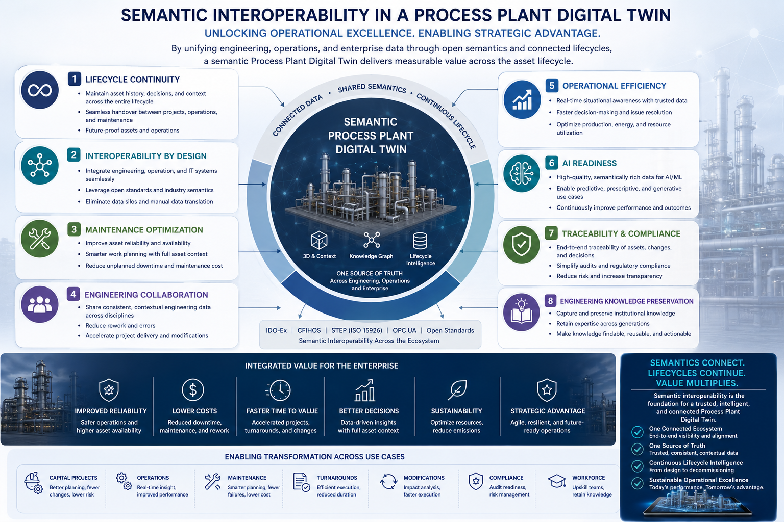
The semantic Digital Twin supports six classes of industrial AI application: (1) Engineering Copilots (P&ID and 3D assist, equipment selection, standards compliance), (2) Contextual AI Reasoning (cause-and-effect analysis, what-if scenarios, constraint reasoning), (3) Semantic Search & Q&A (natural language cross-domain queries, similarity and recommendation), (4) Intelligent Maintenance (anomaly detection, remaining-useful-life prognostics, failure prevention), (5) Operations Copilots (real-time situation awareness, alarm analysis, operator guidance), and (6) Enterprise Insights (asset performance intelligence, reliability analytics, KPI and compliance reporting). These applications operate through an AI Orchestration Layer providing agent management, task orchestration, goal planning, safety guardrails, and human-in-the-loop oversight. The semantic foundation they depend on includes IDO-Ex/DEXPI semantic grounding, STEP/ISO 15926/IEC 61970 lifecycle standards, CFIHOS, eClass, QUDT and Schema.org ontologies, entity resolution across domains, and a SPARQL/GraphQL graph query API together with reasoning and inference services.
End-to-End Demonstration Scenario¶
The demonstrated scenario follows a realistic operational workflow in which a fault is detected in an automation system and ultimately results in completed maintenance execution and Digital Twin lifecycle update (Figure 56).
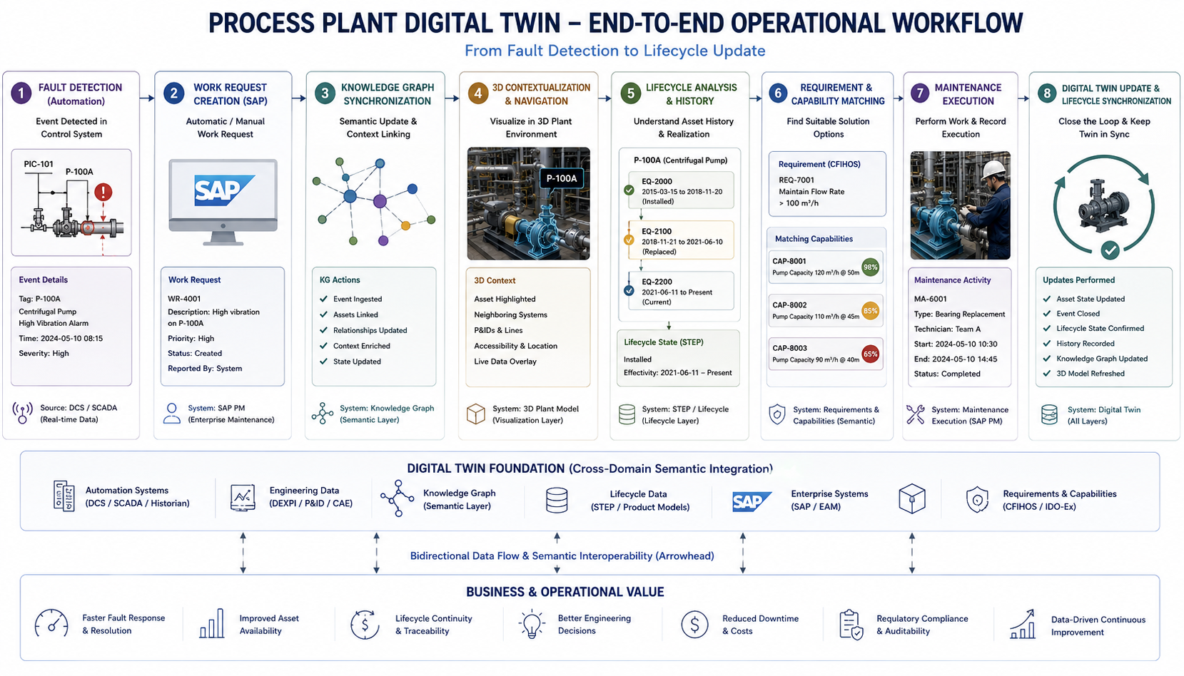
The scenario is grounded in the real Stora Enso paper mill environment. At 08:15 on 2024-05-10, a high-vibration alarm is raised on pump P-100A (Centrifugal Pump, Area 10) by the DCS/SCADA system. Work Request WR-4001 (SAP PM order 4500012345, Priority: High) is created. The Knowledge Graph ingests the event, links it to equipment EQ-2001, updates the asset state, and enriches the context. The 3D model highlights P-100A and overlays live data for neighboring systems. STEP lifecycle history retrieval shows three prior realizations (EQ-2000, EQ-2100, EQ-2200). CFIHOS requirement REQ-7001 (Maintain Flow Rate > 100 m³/h) is matched against available capabilities: CAP-8001 (120 m³/h @ 50 m, match 98 %), CAP-8002 (110 m³/h @ 45 m, match 85 %), CAP-8003 (90 m³/h @ 40 m, match 65 %). Maintenance Activity MA-6001 (Bearing Replacement, Team A) is executed from 10:30 to 14:45 and recorded in SAP PM. The Digital Twin is then updated: asset state confirmed, event closed, lifecycle state updated in STEP, history recorded, Knowledge Graph refreshed, and the 3D model synchronized.
The business and operational value delivered by this scenario includes faster fault response and resolution, improved asset availability, end-to-end lifecycle continuity and traceability, better-informed engineering decisions, reduced downtime and maintenance costs, regulatory compliance and full auditability, and a foundation for data-driven continuous improvement. Figure 57 illustrates the closed-loop synchronization that results from completing these steps.
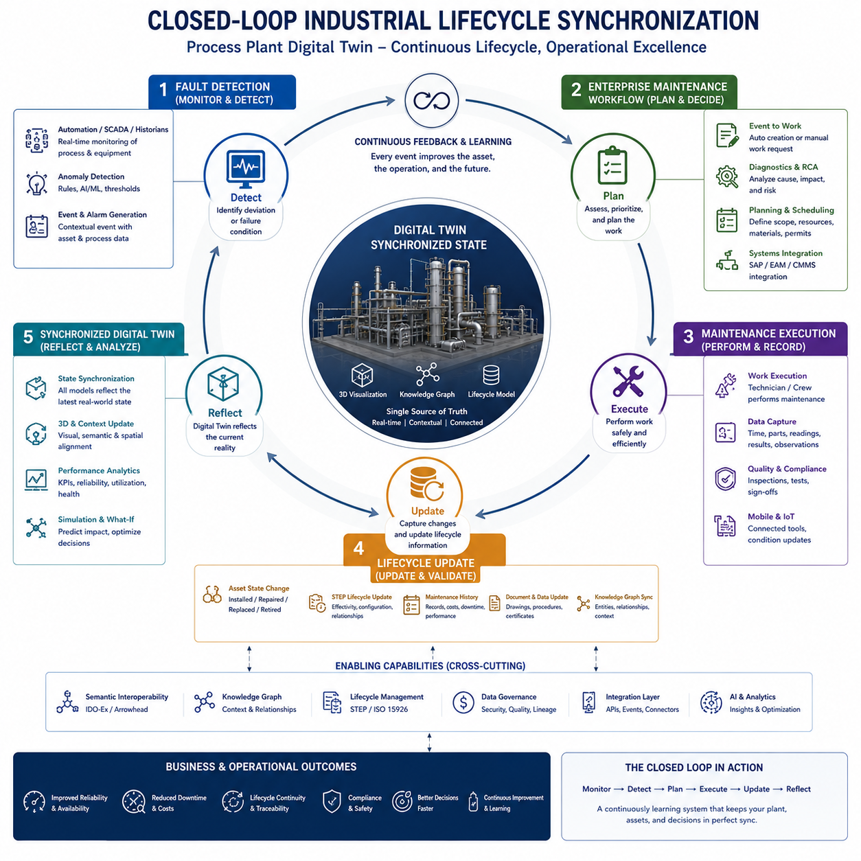
The closed-loop lifecycle synchronization operates in five named phases: (1) Monitor & Detect (real-time monitoring, anomaly detection, alarm generation), (2) Plan & Decide (work request creation, root cause analysis, maintenance planning and scheduling), (3) Perform & Record (maintenance execution, data capture, quality and compliance sign-off), (4) Update & Validate (STEP lifecycle update, maintenance history recording, Knowledge Graph synchronization, document update), and (5) Reflect & Analyze (Digital Twin state synchronization, 3D and semantic context refresh, performance analytics, simulation and what-if analysis). These phases are enabled by six cross-cutting capabilities: semantic interoperability via IDO-Ex and the Arrowhead Framework; the Knowledge Graph for context and relationships; lifecycle management grounded in STEP/ISO 15926; data governance covering security, quality, and lineage; an integration layer of APIs, event streams, and connectors; and AI and analytics for insights and optimization. The resulting business outcomes are improved reliability and asset availability; reduced downtime and costs; lifecycle continuity and traceability; compliance and safety assurance; faster and better-informed decisions; and continuous improvement through every maintenance cycle.
Limitations and Considerations¶
The architecture and approach demonstrated in UC 2.9 are subject to the following limitations and practical considerations:
-
Alignment class curation: The approach relies on a carefully selected, minimal set of high-value classes (Equipment, Functional Location, Tag, System, Lifecycle State) to bridge standards. As standards evolve, these alignment classes require ongoing governance to remain accurate and stable. Expanding the alignment set increases coverage but also maintenance burden.
-
IDO-Ex identity stability: The shared identity layer depends on IDO-Ex concepts remaining semantically stable. Changes to the upper ontology can propagate across all alignment mappings and must be managed with backward compatibility in mind.
-
EXPRESS → OWL transformation complexity: Lifting STEP constructs (AP242, AP239 PLCS) into OWL 2 DL requires specialized modeling expertise. EXPRESS aggregates, subtype constraints, and complex attribute cardinalities do not map trivially to OWL, and the resulting ontology requires validation against the source schema.
-
Proprietary and siloed source data: The architecture assumes a degree of accessibility to engineering data across systems (DEXPI, SAP, STEP repositories). In practice, much of this data is proprietary, fragmented, or held in systems without open APIs, which limits the completeness of the Knowledge Graph.
-
Reasoning performance at scale: Reasoning-based interoperability (automatic class inference, property propagation) becomes computationally expensive as the graph scales to full plant scope across multiple standards. Partitioned or federated reasoning strategies are needed for production deployment.
Conclusions¶
UC 2.9 demonstrates how semantic interoperability, lifecycle-aware Knowledge Graph technologies, and federated industrial architectures can enable next-generation Process Plant Digital Twin environments. The demonstrated use case, based on a real Stora Enso paper mill environment in Sweden, shows how operational systems, engineering systems, enterprise workflows, lifecycle structures, and semantic interoperability technologies can be combined into a coherent lifecycle-aware ecosystem. The Process Plant Digital Twin therefore represents both a practical industrial interoperability solution and a strategic foundation for future industrial intelligence, lifecycle management, and semantically integrated operational environments.